

The reach of industrial inkjet printers ranges from commercial packaging and wide-format graphics to signage, textiles, and electronic applications and enables the information sharing and communication that surrounds our everyday activities. FUJIFILM Dimatix uses multiphysics simulation in the development of the MEMS actuators driving their ink deposition products.
Printing With Micron-Scale Piezoelectric Actuation
Chris Menzel, principal scientist on the research team at FUJIFILM Dimatix, is studying print head actuation in order to design new unimorphdiaphragmm actuators. These actuators are created in a MEMS fabrication process using a high-performance thin-film piezoelectric layer. This layer is a high-quality proprietary sputtered version of lead zirconium titanate (PZT), an electroceramic that changes shape under an applied electric field and is used in many transducers. The PZT is bonded to a silicon membrane and the actuators are then arrayed across the surface of a wafer, with each one corresponding to a tiny jet consisting of flow channels and a nozzle (see figures 1 and 2). Thousands of these systems are packed tightly together in the print head.
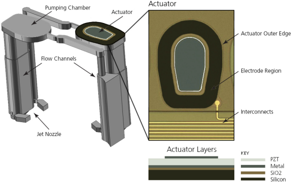
Fig. 1: The print head geometry developed by FUJIFILM. Each actuator sits on top of a pumping chamber containing a reservoir full of ink. Below the chamber are flow channels that carry ink to the nozzle.
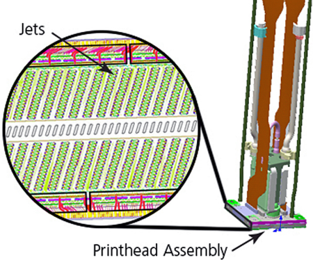
Fig. 2: Magnification of jets on the wafer and their location in the print head assembly.
Next page
The components of each jet (the fluidic channels and the actuator) combine to form a resonant fluidic device. Upon electrical stimulation of the PZT by pulses tuned to stimulate the jet's resonance, the actuator deflects and generates acoustic waves within the closely coupled flow channels. The jet design effectively converts the pressure wave into an oscillating flow, which has to overcome the surface tension at the nozzle in order to throw an ink drop. When the resulting fluid momentum is large enough, the droplet is propelled outward and onto a substrate.
The goal of Menzel's design work is to define an actuator and jet flow channels that combine to generate a droplet meeting a target mass at a given velocity, with a target maximum firing frequency for the available voltage. Implicit in this design process is the need for miniaturization and the associated lower cost. With this in mind, the primary concerns in actuator design are maximizing deflection, minimizing size, and matching the actuator's impedance to the flow channels and the nozzle.
Simulation Reveals Actuator Compliance And Output
A two-stage modeling approach was needed because the actuator performs its function within a jet system. In the first stage, Menzel determined functional parameters for various actuator geometries. He then used these parameters in a complete jet model to determine how the whole system would respond.
A COMSOL Multiphysics software simulation was set up to determine the actuator functionality. Simulations offer an understanding of the relationships between functional parameters and the many layer thicknesses, boundary conditions, and sizes a process can generate. The software's ability to sweep through a large set of these variables and deliver easy-to-interpret results allowed the team to easily optimize total system response, and hence, the print head.
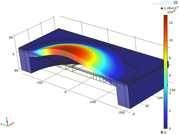
Half of the actuator geometry was modeled along its central axis and included different layers for the silicon, metals, insulators, and PZT (see figure 3, top). Also included were a section of the ink-filled pumping chamber below the actuator and a section of a neighboring flow channel. A simulation was performed to extract the actuator's deflection under a pressure load (known as compliance) and the deflection under a voltage load, known as output (see figure 3, bottom). The study was run over a wide range of actuator geometries. The resulting values were applied to a larger-scale model used for system-level design optimization.
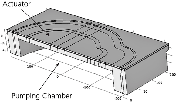
Fig. 3: Top, the software model shows half of the actuator geometry with metal, silicon, PZT, electrodes, and pressurized ink chamber. Bottom, simulation results show the deflection of the actuator.
Looking Ahead To Faster, Smaller Print Heads
The simulation results led to an updated design by providing the information needed to fit a new device to tight specifications and smaller actuator geometries. The multiphysics model revealed valuable information that allowed the engineering team to better understand the ins and outs of their actuator and jet. Modeling remains the starting point for evaluating actuator concepts and product feasibility. The associated reduction in design time is critical to effective and efficient product release. Even higher quality printing will soon be on the market as print head designs, supported by simulation, evolve.
About the Author
Lexi Carver is a technical marketing engineer at COMSOL. She holds an MS in mechanical engineering from Northeastern University.
Related Stories
Actuator Systems Market in Aviation Worth 1090.9 Million USD by 2021
Automotive actuators deliver improvements to next generation haptic accelerator pedals
Conductive Inks and Paste: Everything is Changing