

Introduction
This Sensors Insight describes a variation on a fluorescent long-line fiber-optic position sensor that the author published in Sensors Magazine in 2005. Briefly, that sensor uses fluorescence radiation generated within a fluorscer-doped, plastic optical fiber to detect the position of the object that sends pump light into the sensor fiber at essentially one point.
The fluorescence radiation travels toward either end of the fiber from the point of excitation. As a result of absorption, the ratio of the signals at the two ends is an exponential function of the two distances traveled. Thus, this ratio is a direct indicator of the position of the object. Although the laboratory proof-of-principle experiment worked as expected, the absorption was many times that from the same fiber, not doped with fluorescers. Apparently, the fluorescers act as very effective scattering centers in their standard concentration found in these fibers. Thus, they produce high sensitivity over a limited range of position.
Expanding the range would require a more powerful source pump light, a reduced concentration of fluorescers, or both. Reducing the concentration of the fluorescers would require the creation of a custom fiber and would thus be expensive.
The variation presented here involves the use of a side-emitting, clear plastic fiber that can be made in house from a conventional plastic fiber. By its nature, the fiber would also be side-receiving, as required for the operation of the sensor. It would be made by creating longitudinal or circumferential scratches in the surface of the fiber that would scatter light out of and into the core.
Analogous to diffraction-grating coupling of light laterally between waveguide structures or microbends in optical fibers for a similar purpose, the depth and spatial frequency of the scratches would determine the effectiveness of the scattering process. These characteristics of the scratches could be varied along the length of the fiber to tailor the positional response of the sensor, if desired. They could be created using sandpaper of a particular roughness or a similar metallic surface, for greater precision. The former was used to generate the preliminary data presented later in this paper.
Next page
The Side-Emitting Fiber
The side-emitting fiber was made from a plastic fiber manufactured by Toray Raytella. It had core and cladding diameters of 1480 and 1500 µm, respectively, with a PMMA core and a fluorinated cladding that resulted in a numerical aperture of 0.63. For a laboratory proof-of-principle, the scratches were made manually, using 180 grit sandpaper, and were circumferential.
It was felt that the process of making the circumferential scratches, which are directed across the fiber, would be easier to control and would, therefore, produce be more uniform along the fiber, which was 236-cm (93-in.) long. Since, in normal operation, the sensor is expected to measure position continuously, a good simulation of that operation would have involved a continuous array of scratches from one end of the fiber to the other. However, it was easier to make a discrete series of such scattering centers, which were equivalent to a continuous array having a shallower depth. The light source for the experiment was an amber Luxeon Star LED, having a peak emission wavelength around 591 nm.
Next page
Experimental Arrangement
Figure 1 is a schematic of the experimental arrangement. It consists of the 236-cm long plastic fiber in which scratched sections were made, approximately 1.3 cm (~ 0.5") long and separated by about 10 cm (~ 4"). At each end of the fiber is a photovoltaic photodetector/op amp combination from OSI Optoelectronics.
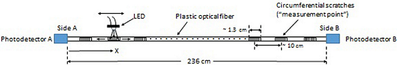
Fig. 1: Experimental arrangement for a proof-of-principle demonstration of the use of a homemade side-emitting fiber in long-line position sensing.
The goal is to determine the ratio of the two signals, Sig. A/Sig. B, when light from the LED is scattered into the fiber at each measurement point. Some of it is also scattered out of the fiber at each measurement point down the line. Ideally, the ratio would be an exponential function of x, if the defective sections of the fiber were identical and that the coupling of the light into the fiber did not vary from one measurement point to another.
The result would be a straight line on a semi log plot of signal ratio vs. position. Although that is an unrealistic expectation at this stage of development, the data in Figure 2 indicate that the manual construction of the measurement points were not far off the mark.
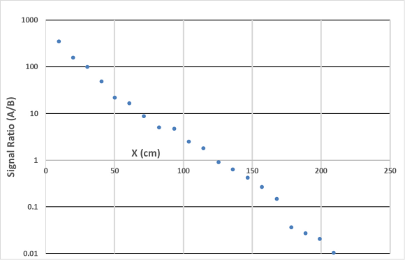
Fig. 2: Signal ratio (A/B) vs. position of the emission points, demonstrating near ideal behavior on a semi log scale.
Next page
Figure 3 is a photograph of the homemade side-emitting fiber when LED light is launched at one end. The bright area is the result of some of that light bypassing the fiber, as well as extremely bright emission from the first few measurement points.
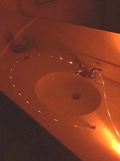
Fig. 3: Photograph of emission from the side emitting fiber when LED light is launched from one end. Very little side emission occurs except at the measurement points.
The photograph comprising Figure 4 shows the continuous emission resulting from adding scratches connecting the first few measurement points.
x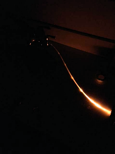 x
x
Fig.4: Photograph of continuous emission from a section of the fiber resulting from added scratches between measurement points.
Conclusion
We believe that the content of this paper demonstrates the efficacy of an in-house, side-emitting fiber for long-line, fiber-optic position sensing and, potentially, other forms of fiber-optic sensing.
About the Author
Jonathan D. Weiss earned a PhD.in physics from the University of Illinois in Urbana, Illinois. He is currently the Chief Technology Officer for JSA Photonics LLC, a New Mexico high-tech company that specializes in refractometers for inline process control and the measurement of battery state-of-charge. Previously, Jonathan worked at Sandia National Laboratories, where much of his work involved the invention of optical sensors of various kinds. He holds 17 patents for such devices, several of which have been licensed. Before that, he worked as a civilian scientist at the Air force Research Laboratory. He earned a PhD.in physics from the University of Illinois in Urbana, Illinois.
Related Stories
A Fluorescent Long-Line Fiber-Optic Position Sensor
ON Semiconductor CCD Image Sensor Expands Options for Astrophotography and Scientific Imaging
Full-Spectrum Sensor Detects ANY Change in Appearance