

Mesh networking has great promise, but you need to understand the subtleties involved to effectively use a mesh network to meet your goals.
Mesh networking is the hot new thing, whether it?s of the wired or wireless type. Mesh-networked wireless sensor systems promise an easy way to deploy nodes in various physical environments, and while this topology does offer operational performance improvements over its counterpart topologies, there are inherent limitations that you should understand before adopting this information delivery method. This article aims to bring a little real-world experience and perspective to the topic?a sanity check?to help you understand some of the subtle ramifications involved in using this networking scheme.
Standard Network Topologies
As a base of reference, the topologies used in wireless networked sensor systems default to one of the top four (see Figure 1).
 |  |
 |  |
| Figure 1. Networking topologies have traditionally fallen into either a bus (A), a ring (B), a tree (C), or a star (D). Realistic implementations of ?networks of networks? may involve a combination of these. | |
Each form has its advantages and disadvantages, though the star topology appears to be the most common player in the wireless networking space.
The most recent addition to the wireless networking family revolves around an ad hoc distribution of network nodes. This situation, typified by a mesh network shown in Figure 2, imposes an additional requirement on the individual nodes: They must agree to pass on messages from their nearest neighbors.
 Figure 2. These are classic forms of mesh networks. Notice that if the coordinator can receive signals from each node, the network topology defaults to a star. |
In some applications information may be completely inside the mesh network (e.g., a light switch activating a light); in other applications, information must be presented to ?the outside.? The ZigBee Alliance nomenclature defines a network coordinator that may be the natural choice for presenting this information to the rest of the world, but other devices with a long-haul or broadband network link may fill this role as well. We?ll call this device the ?data gateway.? The sources of the information, i.e., the sensors and radio transceivers, are referred to as ?end devices.? The routers serve as repeaters. Notice that if each end device communicates directly with the data gateway, the ?mesh? reverts to the classic star topology.
In a real-world mesh network, the network provides each node with multiple data transmission paths, forming a mesh. Each node communicates its existence as well as other information with its neighbors, allowing various algorithms to determine the best way to transmit end-device data to the network coordinator. Some networks communicate this information on demand, when a message needs to be sent, while others maintain it actively. In either case, transmission of network information takes up bandwidth, reducing the maximum bandwidth available to the sensor.
Attenuation
The performance of a link in a star network is dictated by the link quality between the access point (base station) and the end node. For a fixed data rate, the bit error rate increases as the received signal strength decreases. Figure 3 shows physically identical structures with interior walls constructed of either cinder block or standard sheet rock.
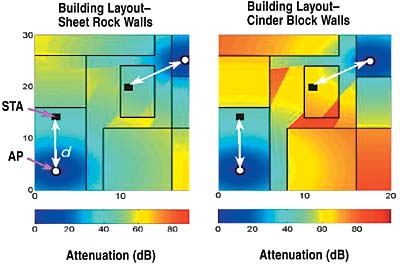 Figure 3. Signal attenuation at 2.4 GHz is measured for two identical structures made out of different materials: one of cinder block, the other of sheet rock. |
Note how the attenuation levels for a 2.4 GHz signal differ between the two materials. In certain instances the structure can cause attenuation exceeding 80 dB! A wireless network using a star topology would have more difficultly operating in such an environment. Without changing the overall networking topology, adding more access points/base stations and/or increasing the transmitter power (or receiver sensitivity) increases performance. Altering transmitter power or receiver sensitivity is harder to implement for commercial off-the-shelf components, so you need more access points to achieve the required performance level.
A mesh network, with its associated relaying of nearest neighbor?s data, reduces the problems frequently found in attenuation-dominant locations since you can place additional network nodes to route the data signal through such an attenuation maze.
| Distance r | 868 MHz | 915 MHz | 2.45 GHz |
| 0.3 m | 18.6 dB | 19.0 dB | 27.6 dB |
| 1 m | 29.0 dB | 29.5 dB | 38.0 dB |
| 3 m | 38.6 dB | 39.0 dB | 47.6 dB |
| 10 m | 49.0 dB | 49.5 dB | 58.0 dB |
| Figure 4. Here?s a comparison of attenuation levels at three common RF frequencies. | |||
Multipath
An electromagnetic wave travels ~1 ft./ns. Having the same signal take multiple paths from transmitter to receiver leads to the insidious problem of multipath. Consider the situation depicted in Figure 5, where a ?clean? 0/1 data signal leaves the transmitter.
 Figure 5. From a multipath perspective, the arrival at the wireless node of the same signal time-shifted is due to ?pieces? of the signal taking different paths from the transmitter to the receiver. |
As it travels to the receiver it physically spreads out and illuminates an area larger than that subtended by the receiver. Some of the signal not already intercepted by the receiver reflects off nearby structures and is redirected toward the receiver.
In the case of two signals arriving at the receiver, as depicted in Figure 6, it?s difficult for the receiver to determine if the actual transmitted signal is a 0 or a 1.
 Figure 6. The net result of multipath is to distort the actual data waveform. |
A mesh network, and its relaying of nearest neighbor?s data, reduces the problems of multipath by reducing the power radiated from each node. Less radiated power means decreased separation distance between adjacent nodes and less multiple reflection delay spread (because faraway signals, or those with reduced reflection intensities, are more difficult to detect), lowering the multipath distortion.
Bandwidth
The idea that ?we don?t wear out our voices because we pass on the message from our neighbors? is used by mesh networks to reduce overall power consumption since no single RF transceiver needs to span the entire distance from node to access point (or data gateway).
Given the data rates identified in 802.15.4, namely 250, 40, and 20 Kbps, ample bandwidth would seem to be available for most sensor applications. Adopting a mesh topology to relay information from the end devices to the data gateway requires that each RF transceiver be able (and willing) to pass on its neighbors? messages. In addition, as transceivers join and/or leave the network (perhaps due to entering or exiting a sleep mode) considerable topological information flies around the network. The net result is similar to that found in Industrial Ethernet, where although the stated system bandwidth may be 100 Mbps, the real data rate is perhaps 1?10 Mbps to minimize network traffic collisions.
In the mesh, residual bandwidth must be allocated to transmit neighbors? messages. The net result is to limit the bandwidth available to each end device to typically 1%?10% of the stated specification. In other words, while network traffic may be zinging along at 40 Kbps, each sensor may have available only 400 bps to 4 Kbps of bandwidth. Given that most sensors are measuring/monitoring relatively slowly varying physical parameters at about 1?10 samples/min., data bandwidth requirements may be low. But in cases where more data are emerging from the sensor, you must understand that each end device doesn?t have access to the full bandwidth.
Coexistence
The technical specifications for IEEE standard 802.15.4 state that a compliant device may transmit within 1 channel in the 868 MHz range, 10 channels in the 915 MHz range, or 16 channels in the 2.4 GHz range. Numerous center-frequency channels have been specified for WiFi (802.11.b) operating in the 2.4 GHz range. However, the overlap of these bands leads to network operation at nonoverlapping channels to minimize co-channel interference.
Radiated Power, Antenna Patterns, and Spatial Overlap
From a power consumption standpoint, the lower the transmitted or radiated power, the lower the power consumption. Yet the lower the radiated power, the smaller the footprint of the transmitted signal. (The outer rim of the footprint shows where the received signal from the transmitter just meets the minimum signal level required for the receiver to operate at acceptable bit error and data rates.) Therefore, the smaller the footprint, the closer the mesh network nodes must be to one another. While antennas can play a key part here, using a high-gain antenna comes at the expense of tighter transmitter-receiver alignment (the pointing and tracking problem). For a fixed output power and receiver sensitivity, a higher gain (higher directionality) antenna allows for increased receiver-transmitter separation, but the antennas must be more accurately pointed. This presents difficulty in practical mesh deployments, which typically expect that nodes can be placed without an extensive site survey.
A radio from another system operating with the same center frequency as an 802.15.4 radio may present interference to the 802.15.4 system. The biggest problems occur when the interfering radio is physically close to an 802.15.4 radio (within 1?2 m); in this case, the 802.15.4 radio may not be able to hear its other 802.15.4 neighbors.
For a mesh-delivered 802.15.4 wireless sensor network, this means that, in physical locations where WiFi-802.11 systems exist, it?s highly recommended that either the 802.15.4 transceivers operate in channel 25 or 26 or be set for an unused frequency band that doesn?t overlap with the operating WiFi system. Otherwise those nodes too close to an active 802.11 station may not be able to hear the rest of the network.
Power Consumption and Network Topology
For a true mesh-networking situation, consider what each transceiver must do. The microprocessor attached to the radio must coordinate the network to know which nodes are in range and which have dropped out, and flow the resulting routing table around the network. It must also coordinate the injection of any sensor data into the transmitted data frame at the correct window and listen for incoming messages. With direct-sequence spread-spectrum radios, such as those specified by 802.15.4, receive power is similar to transmit power because of the power-hungry correlator circuitry that must be running in receive mode. While the transmitter may frequently not operate, the receiver is usually continually operating in listening mode. For optimal power consumption, put the RF section to sleep. In a star topology where the access point is always on, end devices don?t have to relay any other communications and can wake up or turn off as they choose. In this situation, the amount of time that the RF section is operating dictates overall power consumption.
In a mesh network, this is more of a problem because devices must be awake and listening to fulfill their obligation to relay. Without some form of synchronization, the devices must resynchronize with the network upon waking and in essence reform the mesh network. This requires a significant amount of over-the-air network traffic, consuming energy and taking time. Several mechanisms are being considered to address this, including total network synchronization and per-hop local synchronization.
Healthy Skepticism
The ZigBee marketing requirements offer a side-by-side comparison of various wireless information delivery methods and include tables such as shown in Figure 7.
| Market Name Standard | GPRS/GSM 1xRTT/CDMA | Wi-Fi 802.11b | Bluetooth 802.15.1 | ZigBee 802.15.4 |
| Application Focus | Wide area voice and data | Web, email, video | Cable replacement | Monitoring and control |
| System Resources | 16 MB+ | 1 MB+ | 250 KB+ | 4–32 KB |
| Battery Life (days) | 1–7 | 0.5–5 | 1–7 | 100–1000+ |
| Network Size | 1 | 32 | 7 | 255/65,000 |
| Bandwidth (KB/s) | 64–128+ | 11,000+ | 720 | 20–250 |
| Transmission Range (m) | 1000+ | 1–100 | 1–10+ | 1–100+ |
| Success Metrics | Reach, quality | Speed, flexibility | Cost, convenience | Reliability, power, cost |
| Figure 7. This is a side-by-side comparison of a few methods of transmitting wireless data. | ||||
These high-level requirements cover some important engineering subtleties that can be understood only after you understand how a mesh network works.
For example, you must evaluate frequency choices and range consequences against international regulations: 868/915 MHz signals propagate better, but 2.4 GHz is usable in most of the world.
Similarly, achievable battery life is driven by latency requirements and application deployment specifics: A system that can afford to send data only every 30 s will last much longer than a system that must send data every second; a system that has access to a powered backbone can do away with synchronization requirements.
Network scalability is another complex issue. Both large (thousands of nodes) and dense (hundreds of neighbors) networks present challenges, as does the maximum number of hops that data can travel. Understanding your application requirements lets you evaluate the technology?s ability to meet them.
Many companies are working through the ZigBee Alliance to meet the needs and expectations of the marketplace. Over the next few months, expect engineering reality to mesh more and more with market requirements.