
Precision industrial processes increasingly rely on efficient and consistent operation of motors and associated machinery. Imbalances, defects, loose fittings, and other anomalies in the machinery typically translate into unwanted vibration, leading to decreased precision, as well as possible safety concerns. If left unaddressed, besides the performance and safety issues, loss of productivity becomes inevitable if the equipment needs to be taken offline for repair.
Condition-based predictive maintenance is a proven approach for avoiding productivity loss by signaling early warning signs of problems, but its value is matched by its complexity. While transducers exist to capture machine vibration, given the unique characteristics and dynamics of any given machine type, it is a daunting task to select the right type of transducer with the appropriate specifications for bandwidth, sensitivity, and range. Implementing a complete sensor processing solution around the selected sensor, one capable of accurately representing the machine vibration, is equally challenging. The placement of the sensor, whether embedded or temporary, can determine the validity of the data and, if embedded, also requires design attention to power, data transmission, and interference sources. Finally, making sense of the captured data is a nontrivial task, which typically requires extensive post-processing and analysis to understand. Existing predictive maintenance methods—using simple piezo-based sensors mounted to the machinery and handheld data-collection tools—have limitations, particularly when it comes to analyzing the vibration data and isolating error sources.
The ideal solution is to have a complete detection and analysis system that can be embedded on or in the machinery and that can act autonomously. We'll explore these limitations and describe the characteristics of an ideal system.
Repeatability of Measurement
Handheld vibration probes offer some implementation advantages: they do not require any modification to the end-use equipment; they are relatively highly integrated; and their large size allows sufficient processing and storage. However, a major limitation is the repeatability of the measurements. Slight differences in the probe location or angle will produce inconsistent vibration profiles, making time comparisons inaccurate. Thus, the maintenance technician is left with the question of whether an observed vibration shift is due to an actual change within the machinery or just a change in the measurement technique. In an ideal system, the sensor would be both compact and sufficiently integrated to allow direct and permanent embedding within the piece of equipment to be monitored.
Scheduling Measurements
Another limitation of the handheld probe approach is the lack of real-time notification when troublesome vibration shifts occur. The same is true for most piezo-based sensors that are typically at a low level of integration (transducer only, in some cases), with the data transferred elsewhere for later analysis. These devices require external intervention and can therefore miss transient events or shifts, or at least delay notification. In contrast, an autonomous sensor processing system that includes sensor, data analysis, storage, and alarm capability, and is still small enough for embedding, offers fast notification of vibration shifts, as well as the ability to show accurate time-based trends.
Understanding the Data
Achieving the ideal of real-time notification from an embedded sensor is possible only if frequency domain analysis is employed. Any given piece of equipment typically has multiple sources of vibration such as bearing defects, imbalance, and gear mesh, in addition to by-design sources such as those caused by a drill or machine press during normal operation. A time-based analysis of the equipment's vibration signature produces a complex waveform that combines these multiple vibration sources and provides little easily discernible information prior to FFT analysis. Most piezo-based sensor systems rely on external computation and analysis of the FFT. This eliminates the possibility of real-time notification and adds a substantial design burden on the equipment developer. By performing an FFT analysis at the sensor, vibration shifts can be isolated immediately to specific sources. Such a fully integrated sensor element could also reduce development time for equipment designers by 6 to 12 months.
Accessing the Data
Embedded FFT analysis assumes that the analog sensor data have been conditioned and converted to digital values, simplifying data transmission. In fact, many vibration sensor systems in use today are analog output only, leading to signal degradation during transmission as well as requiring offline data analysis. Given that most industrial equipment requiring vibration monitoring tends to exist in noisy, moving, inaccessible, and even dangerous environments, there is a strong desire among both equipment designers and operators to reduce the complexity of interface cabling and to perform as much of the data analysis as possible at the source to capture the most accurate representation of the equipment vibration as possible.
How Much Data
Many existing sensor systems use single-axis piezo transducers that provide no directionality information, and thus limit the understanding of the equipment vibration profile. The lack of directionality—the ability to isolate a vibration source to a particular axis—translates to the need for very low-noise sensors, which also affects the cost. The availability of triaxial MEMS-based sensors, if precision-aligned across each sensing axis, significantly increases our ability to isolate the vibration source, while potentially decreasing the cost.
Probe Points
The question of where to place sensors is extremely important, but highly dependent on the type of equipment, its operating environment, and even its life cycle. If cost constrains the number of possible probe points to a few or one, probe placement becomes critical. This translates to either significant additional up-front development time to determine optimal probe placement through experimentation or leads to some compromise in the amount and quality of the data to be captured. More fully integrated sensor probes offered at a much lower cost will allow designers more flexibility in optimizing their condition monitoring program; they can place multiple probes per system, with a lower up-front development time and cost, or use fewer and less costly sensors to capture accurate single-point data.
Equipment Life-Cycle Shifts
While the transducer element is an important consideration—regardless of sensing technology used—the sensor signal conditioning and processing wrapped around the transducer is typically more important. The signal conditioning and processing is specific to the piece of equipment as well as to its life cycle. This translates to several important considerations in the design of the sensor. First, earlier A/D conversion (i.e., conversion at the sensor head, versus off-equipment) allows for in-system configuration and tuning.
The ideal sensor would provide a simple programmable interface to simplify the equipment set-up, through the use of quick baseline data captures, manipulation of filtering, programming of alarms, and experimentation with different sensor locations. With existing simple sensors, to the extent that they may be configurable at equipment set-up, some compromise in sensor settings still must be made to accommodate changes in the maintenance priorities over the life of the equipment. For example, should the sensor be configured for early life when equipment faults are less likely or for its end-of-life when faults are not only likely but potentially more detrimental? The preferred approach uses an in-system programmable sensor that is configurable to adapt to changes in life cycle. For instance, during early life it could be configured for infrequent monitoring for the lowest power consumption. Later, it could be reconfigured to perform more frequent, user-programmed monitoring once a vibration shift (warning threshold) has been observed. In either case the captured data require monitoring for, and interrupt-driven notification of, user-programmed alarm thresholds.
Identifying Shifts/Trends
The earlier discussion on adapting the sensor to changes in the equipment's life cycle is somewhat dependent on knowing the equipment's baseline response. Simple analog sensors can allow this, assuming the operator takes measurements, does the off-line analysis, and stores this data offline and properly tagged to both the specific piece of equipment and the probe location. A preferred and less error-prone approach would allow baseline FFT storage at the sensor head, thus eliminating any potential for misplaced data. The baseline data also helps with establishing alarm levels that, again, would ideally be programmed directly at the sensor. In any subsequent data analysis/capture where warning or fault conditions are detected, a real-time interrupt can then be generated.
Documentation/Traceability
Within a factory setting, a proper vibration analysis program may involve monitoring tens or even hundreds of locations, whether using a handheld probe or an embedded sensor. Over the course of the lifetime of a given piece of equipment, this may require the capture of thousands of records. The integrity of a predictive maintenance program depends on the proper mapping of data to the location on the equipment and the time at which the data were collected. A sensor that has a unique serial number and the ability to time-stamp the data, in addition to embedded storage, aids in this endeavor.
Sensor Reliability
Our earlier discussion highlights methods to improve existing sensor-based approaches to vibration monitoring for predictive maintenance. However, what if the sensor becomes faulty rather than the equipment? Or, if operating with a fully autonomous sensor (as described as the ideal), how confident can we be that the sensor continues to work at all? With many existing transducers, such as piezo-based, these situations present a serious limitation because simple piezo sensors have no means of providing an in-system self test. There is always a lack of confidence in the consistency of data recorded over time, and in the end-of-life critical monitoring phase where real-time fault notification is time- and cost-critical and can be a significant safety problem; there is always a concern that the sensor could become nonfunctional. An essential requirement of a high-confidence predictive-maintenance program is the ability to remotely self-test the transducer. Fortunately, this is possible with some MEMS-based sensors.
 Figure 1. The ADIS16227 combines a vibration sensor, signal processing, data analysis, and data storage in a compact package |
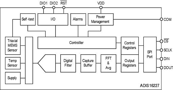 Figure 2. A block diagram of the ADIS16227 industrial vibration monitor |
At its core is a tri-axis wide-bandwidth MEMS-based sensor with a 22 kHz resonance frequency, sample rate configurable up to 100 kHz, and averaging/decimation options for more accurate assessment of subtle vibration profile changes. The MEMS sensor provides a digital self-test mode to provide continuous confidence in its functionality and data integrity. The compact 15 by 15 by 15 mm cube configuration is fully embeddable and programmable, can be placed close to the vibration source, and enables the early detection of small signals in a repeatable way. This avoids data discrepancies due to differences in location/coupling from measurement-to-measurement using handheld devices.
Reducing Barriers to Adoption
The introduction of fully integrated and reliable vibration sensors, with the ability for autonomous and configurable operation, provide developers of predictive maintenance programs with the ability to significantly improve the quality and integrity of the data-collection process, without the limitations and compromises posed by past vibration analysis approaches. With their high level of integration and a simplified programmable interface, these new sensors enable easier adoption of vibration sensing, previously limited to a handful of highly skilled technologists with decades of analytical experience in machine vibration.
ABOUT THE AUTHOR
Bob Scannell, MSCE, BSEE, is a Business Development Manager for Inertial MEMS Products for Analog Devices Inc., Greensboro, NC. He can be reached at [email protected].