Accelerometers are sensing transducers that provide an output proportional to acceleration, vibration, and shock. The piezoelectric accelerometer is the most popular class of these devices; other types are based on piezoresistive, capacitive, and servo technologies.
 |
Piezoelectric Accelerometers
These self-generating devices (see Figure 1) are characterized by an extended flat-frequency response range, a large linear amplitude range, and excellent durability. Piezoelectric materials, whether natural quartz or manmade ceramic, have the ability to output an electrical signal proportional to applied stress. In an accelerometer, the piezoelectric elements act as a spring with a stiffness k, and connect the base of the accelerometer to the seismic masses. The sensor operates on Newton's second law of motion: F = ma. An input at the base of the accelerometer creates a force, F, on the piezoelectric material proportional to the applied acceleration, a, and size of the seismic mass, m. The frequency response (see Figure 2) is determined by the sensor's resonant frequency, ω, which can generally be modeled as a simple single-degree-of-freedom system. It can be estimated by:
 Figure 1. A 3-crystal, shear mode, piezoelectric accelerometer is commonly referred to as a trishear design. This configuration minimizes the effects of thermal transients and base strain. |
There are two categories of piezoelectric accelerometers, defined by their mode of operation. Internally amplified, or integral electronic piezoelectric (IEPE) types, have built-in microelectronic signal conditioning. Charge-output devices incorporate only the self-generating piezoelectric sensing element and have a high-impedance charge output signal.
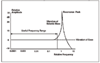 Figure 2. The typical frequency response of a piezoelectric accelerometer is shown as a logarithmic plot. The usable frequency range generally falls along the horizontally "flat" area of the response curve. |
The signal-conditioning electronics in IEPE sensors (see Figure 3) convert the high-impedance charge signal generated by the sensing element into a usable low-impedance voltage signal that can be readily transmitted, over ordinary 2-wire or coaxial cables, to any voltage readout or recording device. The circuitry can also include gain, filtering, and self-test features. Simplicity of use, high accuracy, broad frequency range, and low cost suit IEPE accelerometers for use in most vibration or shock applications. Their upper temperature limit is typically 250°F (121°C), but specialty units can operate up to 350°F (175°C).
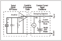 Figure 3. This schematic diagram of a typical IEPE accelerometer measurement system shows the piezoelectric element, built-in signal conditioning circuitry, interconnecting cables, and power supply. |
Charge output sensors provide a high-impedance, electrical charge signal that is generated directly by the piezoelectric sensing element. Because the signal is sensitive to corruption from environmental influences and cable-generated noise, a special low-noise cable must be used. For accurate measurements, the signal must be conditioned into a low-impedance voltage, usually by a charge amplifier or inline charge converter with capacitive feedback, before being input to a readout or recording device. Adjusting the value of the feedback capacitor alters the transfer function or gain of the charge amplifier.
Charge output accelerometers are used when high-temperature survivability is required. For long-distance signal transmisson, an inline charge converter should be placed near the accelerometer to minimize the chance of noise. To reduce system cost, the charge converter can be operated from the same constant-current excitation power source as IEPE accelerometers. A special low-noise cable between the accelerometer and the charge converter will minimize vibration-induced triboelectric noise.
Sophisticated laboratory-style charge amplifiers (see Figure 4) usually include adjustments for normalizing the input signal and altering the feedback capacitor to provide the desired system sensitivity and full-scale amplitude range. Filtering also may be used to tailor the high- and low-frequency response. Some charge amplifiers provide dual-mode operation, which permits their use with either IEPE accelerometers or charge output sensors. For IEPE accelerometers, the unit provides the necessary excitation power for the built-in circuitry.
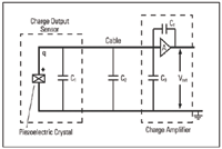 Figure 4. A typical piezoelectric accelerometer measurement system includes the piezoelectric element, interconnecting cables, and charge amplifier for external signal conditioning. |
The high-impedance nature of the output signal of charge output accelerometers requires that high insulation resistance be maintained for the accelerometer, cabling, and connectors by keeping them dry and clean. Doing so will help minimize problems with noise and signal drift.
Configurations. Piezoelectric accelerometer configurations are defined by the way the inertial force of an accelerated mass acts upon the piezoelectric material. The three most prevalent types are shear, flexural beam, and compression.
Shear Mode. Shear mode accelerometers (see Figure 5) sandwich the sensing material between a center post and the seismic mass. A compression ring or stud applies a preload force to create a rigid linear structure. Under acceleration, the mass applies a shear stress to the sensing material. The result is a proportional electrical output that is collected by the electrodes and transmitted by lightweight lead wires to either the built-in signal conditioning circuitry of ICP sensors, or directly to the electrical connector for a charge output type. By isolating the sensing crystals from the base and housing, shear mode accelerometers excel in rejecting thermal transient and base-strain effects. Furthermore, the shear geometry's small size promotes high-frequency response while minimizing mass loading effects on the test structure.
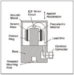 Figure 5. When a basic shear mode accelerometer is accelerated, the piezoelectric material is stressed in the shear direction as the seismic mass generates an opposed force. |
Flexural Beam Mode. Flexural mode designs (see Figure 6) use beam-shaped sensing crystals supported in such a way as to create strain on the crystal when accelerated. The crystal may be bonded to a carrier beam that increases the amount of strain when accelerated. Flexural mode accelerometers are insensitive to transverse motion and well suited for low-frequency gravitational acceleration applications such as structural testing.
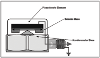 Figure 6. Flexural mode accelerometers are capable of providing high-amplitude signals, but at the expense of being less durable. |
Compression Mode. These well-established accelerometers are simple structures that feature high rigidity (see Figure 7). Upright compression designs sandwich the piezoelectric crystal between a seismic mass and a rigid mounting base, and secure it to the base by means of a pre-load stud or screw. When the sensor is accelerated, the seismic mass increases or decreases the amount of compressive force acting on the crystal, and a proportional electrical output results. The larger the seismic mass, the greater the stress and, hence, the greater the output. This rugged design can withstand high-g shock levels, but due to the intimate contact of the sensing crystals with the external mounting base, upright compression designs tend to be more sensitive to base bending (strain), especially when used on thin sheet metal structures. Additionally, the internal parts expand and contract along the sensitive axis, making the accelerometer more susceptible to thermal transient effects that can contribute to erroneous output signals when used at low frequencies in thermally unstable environments, such as outdoors or near fans and blowers.
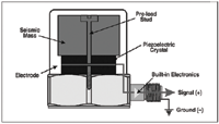 Figure 7. Compression mode accelerometers are low in cost and relatively easy to manufacture. |
Piezoresistive Accelerometers
Single-crystal silicon is an anisotropic material whose atoms are organized in a lattice having several axes of symmetry. The orientation of any plane in the silicon is provided by its Miller indices. A fabrication process developed in the late 1970s takes advantage of advances in silicon micromachining. A single-crystal silicon is grown; the ingot is trimmed, sliced, polished, and cleaned; a deposited film controls the diffusion of a dopant into a surface region of the wafer; photolithography etches the film at places defined in the developing process; the photoresist is removed; and isotropic and anisotropic wet chemicals are used for shaping the mechanical microstructure. The silicon's piezoresistive coefficients are controlled by both the resultant stress distribution in the microstructure and the dopant.
Thin-film metalization provides both the bonding pads and the electrical interconnection of various controlled surfaces formed in the crystal. The wafer is then separated into individual dies, which are bonded by various techniques into the transducer housing. Wire bonding connects the metallized pads to metal terminals in the transducer housing. The strain gauges are interconnected as a Wheatstone bridge that gives them a response down to DC (i.e., they respond to steady-state accelerations). Because the strain gauges are diffused directly into the flexure, these accelerometers use silicon as both the flexural and the transduction element (see Figure 8).
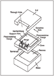 Figure 8. In the MEMS piezoresistive accelerometer shown here, silicon serves as both the flexural and the transduction element because the strain gauges are diffused directly into the flexure. Among the advantages of this manufacturing technique is a high resonant frequency that optimizes the frequency response. |
The stiffness of these accelerometers results in a high resonant frequency that optimizes their frequency response. The reason is that silicon's square root of the modulus-to-density ratio, an indicator of dynamic performance, is higher than that of steel. Other desirable features include extremely small size, large signal amplitudes (semiconductor strain gauges have a gauge factor 25–50 X that of metal), good linearity, and improved stability. A properly temperature-compensated piezoresistive accelerometer has an operating temperature range of –65°F to 250°F.
Capacitive Accelerometers
Capacitive accelerometers are similar in operation to piezoresistive accelerometers in that they measure a change across a bridge circuit. Rather than resistance, however, they measure a change in capacitance. The sensing element consists of two parallel plate capacitors acting in a differential mode. They rely on a carrier demodulator circuit or its equivalent to produce an electrical output proportional to acceleration. There are several types of capacitive elements. One type incorporates a metal sensing diaphragm with alumina capacitor plates (see Figure 9). Two fixed plates sandwich the diaphragm, creating two capacitors. Each has a fixed plate and the two share the diaphragm as a movable plate.
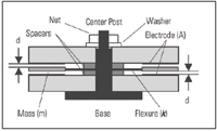 Figure 9. When exposed to acceleration, a capacitive accelerometer undergoes a capacitance shift caused by a change in the distance between the electrodes. This change varies as a result of movement by the flexure, which also serves as an electrode. |
When the sensor is placed in the Earth's gravitational field or accelerated by vibration on a test structure, the spring mass experiences a force proportional to the mass of the spring mass and is governed by F = ma. Consequently, the spring mass deflects linearly according to the spring equation:
 |
where:
X = deflection of spring mass
k = stiffness of spring mass
This deflection causes the distance between the electrodes and the spring mass to vary. The variations have a direct effect on each of the opposing capacitor gaps according to:
 |
and
 |
C = element capacitance
AE = surface area of electrode
= permittivity of air
d = distance between spring mass and electrode
Capacitive accelerometers require a built-in circuit (see Figure 10) that serves two functions: It allows changes in capacitance to be useful for measuring both static and dynamic events, and it converts the changes into a voltage signal compatible with readout instrumentation.
Silicon micromachining techniques can be used to fabricate capacitive accelerometers as well as piezoelectric and piezoresistive types. The single-crystal nature of the silicon, the elimination of mechanical joints, and chemically machining the mechanical stops yield a transducer with a high overrange capability. Using a gas rather than silicone oil as the damping medium extends the damping characteristics over a broad temperature range. A series of grooves and holes in the central mass squeeze gas, whose thermal viscosity change is small relative to that of silicone oil, through the structure as the mass displaces. Capacitive MEMS accelerometers measure acceleration from <2 g's to hundreds of g's and frequencies up to 1 kHz, and can withstand shock levels of 5000 g's or greater. Most incorporate electronics that inject a signal into the element, complete the bridge, and condition the signal. The negative aspects of these accelerometers are a limited high-frequency range, a relatively large phase shift, and a higher noise floor than a comparable piezoelectric type.
 Figure 10. Capacitive accelerometers usually incorporate two capacitors, modulation circuitry, gain, and filtering. |
Servo (Force Balance) Accelerometers
The accelerometers described thus far may be classified as "open-loop" devices. The deflection of the seismic mass, proportional to acceleration, is measured directly using either piezoelectric, piezoresistive, or variable capacitance technology. Associated with this mass displacement is some small, but finite, error due to nonlinearities in the flexure. Servo accelerometers (see Figure 11) are "closed-loop" devices. They keep internal deflection of the proof mass to an extreme minimum. The mass is maintained in a "balanced" mode, virtually eliminating errors due to nonlinearities. The flexural system can be either linear or pendulous. Electromagnetic forces, proportional to a feedback current, maintain the mass in a null position. As the mass attempts to move, a capacitive sensor detects its motion. A servo circuit derives an error signal from this sensor and sends a current through a coil, generating a torque proportional to acceleration and keeping the mass in a capture or null mode.
Servo accelerometers can cost up to 10 3 the price of open-loop types. Their ranges are usually <50 g, and they are accurate enough for use in guidance and navigation systems. For navigation, three axes of servo accelerometers are typically combined with three axes of rate gyros in a thermally stabilized, mechanically isolated package as an inertial measuring unit (IMU). This IMU enables determination of the six degrees of freedom needed for navigation in space. They measure frequencies to DC (0 Hz), and are not usually sought after for their high-frequency response.
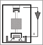 Figure 11. In the servo or "force balance" accelerometer, a feedback loop is established to "force" the system into equilibrium when exposed to acceleration. This forcing energy is measured and is proportional to the applied acceleration. |
Summary
Understanding the operating principles of piezoelectric, piezoresistive, and capacitive accelerometers is the first step toward making the best selection for your application. The next step is to narrow the field of choices by evaluating criteria specific to the intended application, such as the sensor's sensitivity, amplitude, frequency and temperature range, and physical characteristics, along with mounting options and environmental conditions at the installation site. Finally, of course, spend some time with the manufacterers' application engineers.
ICP is a registered trademark of PCB Group, Inc.
This article was excerpted by permission from Chapter 5 of the Sensor Technology Handbook, Jon Wilson general editor, Elsevier Inc., 2005. The rest of the chapter includes comparisons of accelerometer types and typical applications as well as performance characteristics. Also addressed are standards, mounting techniques, probe tips, isolation issues, cables and connections, and recent developments and future directions.
The book can be ordered by calling 800-545-2522 (domestic) or 800-460-3110 (international), or by visiting www.books.elsevier.com/computereng. Use offer code 82016 A to receive free shipping and a 10% discount off the $99.95 cover price.
Craig Aszkler is Vibration Products Division Manager, PCB Piezotronics, Inc., Depew, NY; 800-828-8840, [email protected], www.pcb.com.