
|
We have previously examined the underlying physics of pressure, what it is and the way that units of pressure measurement are derived and related to one another ("Fundamentals of Pressure Sensing," Sensors, July 2002). Now we will investigate the various methods of measuring pressure and the array of instruments designed to carry out that task.
How Is Pressure Measured?
As with most measurands, pressure measurement methods have varying suitability for different applications. Measurement engineers need to be familiar with several techniques in order to select the one that is most appropriate for their specific requirements.
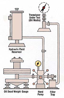
Deadweight Tester. The most fundamental pressure measurement technique, and favored as well for primary calibration of pressure sensors, is the deadweight tester, or piston gauge (see Figure 1). This device uses calibrated weights (masses) that exert pressure on a fluid (usually a liquid) through a piston. Deadweight testers can be used as primary standards because the factors influencing accuracy are traceable to standards of mass, length, and time. The piston gauge is simple to operate; pressure is generated by turning a jackscrew that reduces the fluid volume inside the tester, resulting in increased pressure. When the pressure generated by the reduced volume is slightly higher than that generated by the weights on the piston, the piston will rise until it reaches a point of equilibrium where the pressures at the gauge and at the bottom of the piston are exactly equal. The pressure in the system will be:
| P = W/A | (1) |
where:
| W | = weight of piston plus weights |
| A | = effective area of piston |
|
Fluid Head—Manometers. The height of a column of liquid, or the difference between the heights of two liquid columns, is used to measure pressure head in devices called U-tube manometers (see Figure 2). If a fluid is installed in an open U-shaped tube, the fluid level in each side will be the same. When pressure is applied to one side, that level will go down and the level on the other side will rise until the difference between the heights is equal to the pressure head. The height difference is proportional to the pressure and to the density of the fluid. The U-tube manometer is a primary standard for pressure measurement.
Although many manometers are simply a piece of glass tubing formed into a U shape with a reference scale for measuring heights, there are many variations in terms of size, shape, and material (see Figure 3). If the left side is connected to the measurement point, and the right is left open to atmosphere, the manometer will indicate gauge pressure, positive or negative (vacuum). Differential pressure can be
|
In some versions, the two legs of the U are of different diameters. Some types incorporate a large-diameter "well" on one side. In others, one tube is inclined in order to provide better resolution of the reading. But they all operate on the same principle. Because of the many constraints on geometry of installation and observation, and their limited range, manometers are not practical or effective for most pressure measurements.
Force-Summing Devices. Mechanical pressure gauges and electromechanical pressure sensors incorporate an elastic element called a force-summing device that changes shape when pressure is applied to it (see Figure 4).
The shape change is then converted to a displacement. Of the wide variety of force-summing devices, the most common are Bourdon tubes and diaphragms. Bourdon tubes provide fairly large displacement motion that is useful in mechanical pressure gauges; the lesser motion of diaphragms is better in electromechanical sensors.
 Figure 4. Of the wide variety of force-summing devices used for pressure sensing, the most common is the Bourdon tube. The springs and linkages that convert the device's motion to that of a pointer are designed with adjustments for zero, linearity, and span to permit mechanical calibration. |
The motion of the force-summing device can be linked to a linear variable differential transformer, which acts as the electromechanical transduction element. Alternatively, it can be linked, usually through a motion amplifying mechanism, to the wiper of a potentiomenter. To reduce acceleration error, a balancing mass may be provided.
Mechanical Pressure Gauges. In mechanical gauges, the motion generated by the force-summing device is converted by mechanical linkage into dial or pointer movement. The better gauges provide adjustments for zero, span, linearity, and (sometimes) temperature compensation for mechanical calibration. High-accuracy mechanical gauges take advantage of special materials, balanced movements, compensation techniques, mirror scales, knife-edge pointers, and expanded scales to improve the precision and accuracy of readings. The most accurate mechanical gauges, test gauges, are used as transfer standards for pressure calibration, but for applications requiring remote sensing, monitoring, or recording they are impractical. Their mechanical linkages also limit their frequency response for dynamic pressure measurements.
Electromechanical Pressure Sensors. Electromechanical pressure sensors, or pressure transducers, convert motion generated by a force-summing device into an electrical signal. These sensors are much more useful and adaptable than mechanical gauges, especially when applied in data acquisition and control systems. In well-designed transducers, the electrical output is directly proportional to the applied pressure over a wide pressure range. For rapidly changing—dynamic—pressure measurement, frequency characteristics of the transducer are an important consideration.
Types of Pressure Sensors
Pressure sensors are available with a variety of reference pressure options: gauge (psig), absolute (psia), differential (psid), and sealed (psis). All use a force-summing device to convert the pressure to a displacement, but that displacement is then converted to an electrical output by any of several transduction methods. The most common are strain gauges, variable capacitance, and piezoelectric.
Strain Gauge Transducers. Strain gauge transducers are based on metal or silicon semiconductor strain gauges. The gauges can be discrete units attached to the surface of the strained element or unbonded gauges. The gauge material can be sputtered onto a diaphragm or diffused into a silicon diaphragm structure. The most common force-summing device for strain gauge transducers is the diaphragm, which may be flat or sculptured. Strain gauges are also used on Bourdon tubes and bellows assemblies.
Strain gauges are made of materials that exhibit significant resistance change when strained. This change is the sum of three effects. First, when the length of a conductor is changed, it undergoes a resistance change approximately proportional to change in length. Second, in accordance with the Poisson effect a change in the length of a conductor causes a change in its cross-sectional area and a resistance change that is approximately proportional to change in area. Third, the piezoresistive effect, a characteristic of the material, is a change in the bulk resistivity of a material when it is strained. All strain gauge materials exhibit these three properties, but the piezoresistive effect varies widely for different materials.
Metal strain gauges are networks of wire or patterns of thin metal foil fabricated onto or into a backing material and covered with a protective film (see Figure 5).
 Figure 5. Foil or wire metal strain gauges can be used either bonded or unbonded to sense the strain (displacement) of the force-summing device. The gauges are configured as quarter-, half-, or full-bridges with standard strain gauge power supplies and signal conditioning. They offer a steady-state resonse but suffer from low sensitivity. |
Their design permits the use of a large active length (= large R) in a small area. They are made of specially formulated alloys with relatively large piezoresistive effects. Silicon strain gauges are doped to resistivity levels that produce the optimum combination of piezoresistive and thermoresistive effects. Strain gauge materials are characterized by their strain sensitivity, but when fabricated into strain gauges they are characterized by their "gauge factor," defined as relative resistance change divided by strain:
or
|
(2) |
where:
|
| R | = resistance |
| = change in resistance | |
| L | = length |
| = strain = |
|
Bonded Strain Gauges. Discrete metal or silicon strain gauges are usually bonded (glued) to the surface where strain is to be measured, and provide an output proportional to the average strain in their active area (see Figure 6). The typical gauge factor is around 2; a strain of 1 µin./in. would produce a resistance change of 2 µ![]() /
/![]() . Unstrained resistance ranges from 120
. Unstrained resistance ranges from 120 ![]() to several hundred ohms. Because a significant length of wire or foil is necessary to provide high unstrained resistance, metal strain gauges cannot be made extremely small.
to several hundred ohms. Because a significant length of wire or foil is necessary to provide high unstrained resistance, metal strain gauges cannot be made extremely small.
Unbonded Strain Gauges. Unbonded strain gauge transducers use relatively long strands of strain gauge wire stretched around posts attached to a linkage mechanism (see Figure 7). The linkage is designed such that when pressure increases, half of the wire is
|
Sputtered Strain Gauges. Strain gauge material may be sputtered onto a nonconductive diaphragm to create the strain gauges (see Figure 8). Location and orientation are controlled by masking, and the molecular bond created by the sputtering process eliminates any problems with adhesive bonding. Gauge factors are similar to those of unbonded gauges. Surface preparation and other process controls are quite critical. The fabrication process offers some of the advantages of a silicon diaphragm, such as good linearity and high
|
Semiconductor Strain Gauges. These devices are made of semiconducting silicon. Their gauge factor is dependent on the doping level—more lightly doped, higher resistivity material has a higher gauge factor. However, it also has greater thermal sensitivity, causing both resistance and gauge factor to change significantly with temperature. Most silicon gauges are doped to provide a gauge factor of 100?200, which gives acceptable temperature characteristics. Discrete silicon strain gauges are used just as are metal gauges, glued to the strained surface in the desired orientation to provide maximum sensitivity for pressure measurement. In addition to their higher gauge factor (which provides higher sensitivity), they are also smaller, allowing more miniaturization.
Bonded Discrete Silicon Strain Gauges. Early silicon strain gauge transducers used discrete silicon strain gauges bonded with adhesives to the surface of a strained element. These devices were similar to bonded metal strain gauges, except that the silicon types
|
Diffused Diaphragm Sensors. Discrete strain gauges, metal or or silicon, require tedious microassembly for installation, but diffused diaphragm sensors (see Figure 9) can be fabricated using semiconductor masking and processing techniques. This approach provides precision location and orientation of the gauges for optimum linearity and sensitivity, allows extreme miniaturization, and reduces assembly costs. It also removes the variability of the adhesive and its application.
Sculptured-Diaphragm Sensors. Early diffused silicon diaphragm pressure transducers used a simple, flat silicon diaphragm of uniform thickness. Silicon microfabrication techniques (MEMS) allow great flexibility in the mechanical design of the diaphragm.
|
Variable Capacitance Transducers. When one plate of a capacitor is displaced relative to the other, the capacitance between the two plates changes. If one of the plates is the diaphragm of a pressure sensor, the capacitance can be correlated to the pressure applied to it (see Figure 10). This change of capacitance is either used to vary the frequency of an oscillator or is detected by a bridge circuit. If the dielectric material is maintained constant, this mechanism provides a very repeatable transducer. The primary advantages are low hysteresis; good linearity, stability, and repeatability; static pressure measurement capability; and a quasi-digital output. However, complicated electronics are required.
|
Some designs of PE transducers (ICP or voltage mode) therefore include an integral preamplifier within the transducer's case. The output can then be an amplified (millivolt level) low output impedance signal, greatly reducing cabling problems and simplifying signal conditioning. The integral amplifier requires external power from a constant-current supply, using the same two conductors as the signal circuit. The signal conditioner has a blocking capacitor to block the DC power supply voltage and to transmit an AC signal.
Because the PE transducers are self-generating, dependent on changes of strain to generate electrical charge, they are not usable with DC or steady-state conditions. They have an inherent low-frequency rolloff that is dependent on the signal conditioning's low-frequency time constant.
Their primary advantage is their ruggedness, and, without integral electronics, their usefulness at high temperatures. If not properly compensated, though, they are sensitive to shock and vibration and may exhibit large changes of sensitivity with temperature variations.
|
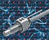 Endevco pressure transducers are available in ranges from 1-20,000 psi in gauge and absolute configurations. Shown here is the 8510B with 10-32 mounting thread and vent tube for standard reference or differential pressure measurements.
Scanners. Multichannel scanning pressure measurement systems are sometimes the best selection when many measurement points are required. Two types are available: mechanical and electronic. Mechanical scanners use only one sensor and mechanically route the pressure sequentially from each measurement point to the sensor. Electronic scanners use many sensors in a common body, and electrically time-multiplex the signals to data acquisition equipment. In both types, tubing transmits the pressure from measurement points to one sensor.
Pressure-Scanning Valves. A pressure-scanning valve is a pneumatic switch capable of sequentially multiplexing a number of pressures to a single transducer. The most common design is based on a matched pair of lapped surfaces with one rotating relative to the other. The transducer is typically flush mounted very close to the valve in order to minimize the volume of gas subject to the changes in pressure. The valve rotor is driven by a stepper motor, and the valve position is indicated by a rotary encoder. A periodic recalibration can be incorporated into the system by supplying accurately known pressures to one or more ports. The maximum scanning rate is dependent on the accuracy required. If the dwell time at each measurement position is long enough for the pressure equilibriým to be achieved, the accuracy is that of the transducer. Equilibrium time is a function of the traveling volume and the magnitude of the pressure change. The typical scanning rate for aerodynamic or jet engine pressure measurements is 5?10 measurements/s. Multiple scanners can be time sequenced to provide faster effective scanning rates.
Electronic Pressure Scanners. ýombining miniature semiconductor strain gauge transducers and solid-state electronic multiplexing into an integrated measurement system provides much higher rates than possible with mechanical scanners. A multiple transducer array, a low-level multiplexer, and an instrumentation amplifier in a shared housing make up the typical system. Some systems also include a pneumatic valve that can be automatically switched to subject each sensor to a calibrated pressure at any time. The calibrated pressure is supplied by a calibration manifold. Because there is no mechanical switching of pressurized passages, there is no need to delay measurements while a traveling volume is stabilized. Each transducer is always measuring, and its output is periodically sampled by the electronic multiplexer scanning. Scanning speeds can be 10,000 to 20,000 sps. Of course, the connecting tubing between the measurement point and the sensor will still impose a physical low-pass filter.
Summary
This discussion of pressure measurement methods and the various sensors available to implement them will, we hope, be of assistance to engineers designing a system from the bottom up as well as those who simply wish to add a component to an existing system.
This article was adapted from Dynamic Pressure Measurement Technology, edited by Jon S. Wilson and published by the Endevco Division of Meggitt Corp. Used by permission.