
The need for improved safety and process efficiencies is driving the development of new sensor systems in industrial and consumer applications. To generate stable and accurate measurement values the signal input to the sensor has to be kept consistent, particularly when the environmental inputs to the sensors are continuously changing. This article describes a versatile, low-cost, high-performance micropump system that opens up new design possibilities for both liquid and gas sensor systems.
From a commercial standpoint, the key feature of the micropump system is its cost, the unit price of which is defined in terms of several dollars rather than tens or hundreds of dollars. The cost profile changes the way sensor systems can be designed and implemented. For example, the low cost can provide the justification for wider distribution of sensors in a particular application, increasing the number of data points and leading to more effective acquisition of sensor data than is the case when a higher cost limits the number of sensors used. In addition, the micropump can be designed into handheld, portable devices.
Where active pumping mechanisms are deployed in sensors, it is often the case that the pump's cost, energy consumption, and size are the determining factors in the design of these systems. Even with so-called "micropumps," where the volume of pumped media is relatively low, the size and cost of many types of micropumps limits their flexibility with respect to being designed into sensor systems. The two-stage, diaphragm, piezo-actuated micropump system described in this article is currently in high-volume production and solves several key issues: cost, size, robust but simple design, energy consumption, broad chemical resistance, good performance with dual pumping stages, and modular design for flexible integration into a variety of systems.
Functional Principles
The key technical features of the micropump (Figure 1) are based a dual-membrane pump mechanism actuated by a double configuration of piezo elements in combination with passive valves. Only a single polymeric material, polyphenylene sulfone (PPSU), comes into contact with the pumping medium. Regarding medical-field applications, the material is certified in accordance to ISO 10993 and USP class VI.
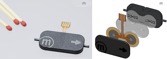 Figure 1. The m-6 micropump (A) and an exploded view of the micropump components (B) |
Figure 2 shows the pumping mechanism. A piezoceramic (shown in blue) mounted on a brass membrane (shown in purple) causes the membrane to flex downward when a voltage is applied, squeezing the fluid (liquid or gas) out of the pump chamber. The check valves on either side of the chamber define the direction of flow. When the voltage decreases, the piezoceramic's corresponding deformation causes the membrane to flex upwards, sucking in the fluid and refilling the chamber. The pump can perform several hundred such pumping cycles per second. The pumping performance can be optimized for a particular application's requirements by adjusting three parameters: amplitude, frequency, and the waveform of the electric control signal. An advantage of piezo pumping technology is that no heat is generated during the pumping cycles.
 Figure 2. A diagram of the pumping mechanism. As the voltage applied to the piezoceramic material (blue) on the membrane (purple) changes, the membrane flexes up, sucking fluid into the pumping chamber, and down, expelling the fluid |
A Gas Sensor Example
In a customer application, the dual piezo-actuated micropump has been used to monitor a gaseous mixture of hydrogen, oxygen, and nitrogen. Using a bypass channel, gas was extracted for analysis and fed to the semiconductor-based metal oxide sensor. Because these types of chemical sensors can be sensitive, an active or continuous sample delivery can be very useful in improving the quality of the data.
During the system evaluation of the micropump, characteristic flow rates based on the pump's driving voltage and frequency were determined as shown in Figure 3A. The graph in Figure 3B shows the relationship between the relative sensor signal and the gas flow, showing an improvement in the signal with the pump actively feeding gas to the sensor. Using the pump also provided a stable flow rate throughout the measurement period. As the graph demonstrates, although the increase in the signal is stronger for some sensor types than others, in general, an active flow to the sensor has a positive effect on the signal strength.
 Figure 3. A graph of the effect of active flow on two different chemical sensors. Graph A shows the micropump's flow rate based on the driving voltage and frequency while graph B shows the relationship between the relative sensor signal and the gas flow |
As a compromise between extracted gas volume and sensor sensitivity, a flow rate of 7 mL/min. was chosen for the final system. The pump's modular design allowed the pump manufacturer to develop customized driving electronics for the pump module based on the customer's application-specific needs, tailoring the driving parameters to optimize energy consumption.
Key Design Features
The pump's simple design integrates numerous features into a few injection-molded components, which means that the dual-membrane micropump systems can be produced at a low cost. Repeatable, highly automated and controlled manufacturing processes, allow for traceability and reliability. Rigorous attention to quality allows the micropump systems to be used in critical applications, including those in the medical field. The micropump's modular design allows it to be easily integrated into a range of systems to provide fluid transport by supplying a continuous flow of the target sample to the sensor. The design platform allows for customization to optimize cost performance in cost-sensitive, large-volume applications for relatively low development charges.
The two actuator stages have been combined in a single pump for the first time. The device can pump both liquids—to 120 cp (about 30 weight oil)—and gases. With water, the maximum flow rate is 6 mL/min. for a single micropump operating at 100 Hz. However, you can place several pumps together, multiplying the flow rate accordingly. For gases, the pump has a maximum flow of 18 mL/min. for a single device.
For pumping liquid media, the dual-membrane mechanism works against a back pressure up to 8 psi (550 mbar). For devices requiring higher back pressure (e.g., in complex fluidic systems with higher capillary forces or filtering functionalities), positioning two of the dual-membrane micropumps in series can double the back pressure to 16 psi. The flow accuracy is ±15% at 100 Hz, which can be increased, if necessary. In addition, the double actuator principle ensures self-filling, improving the self-priming of the pump at startup. The device also has a high tolerance for bubbles and can pump gas-liquid mixtures. Performance is maintained under imperfect conditions, with a relatively high tolerance to particles when pumping liquids. By using the available evaluation kits, you can test the pump's performance in the target application and define its driving parameters.
With its small dimensions (30 x 15 x 3.8 mm; see Figure 4), and especially its low height, the pump can be used as a subassembly integrated on a fluidic chip. Greater space savings can be achieved by placing parts of the pump directly into the injection-molded parts of the fluidic chip. Depending on the fluidic chip's design, it is also possible to integrate the micropump as an OEM component into the read-out unit. In such applications the pumping can be carried out, for example, with an air buffer between the pumping fluid and the pump to avoid contamination. To create an air buffer, the micropump generates a vacuum, sucking air into the pump. When the sampling inlet is introduced into a liquid, a liquid sample is taken, which can then be transported to the sensor. If the sensor is mounted sufficiently far in front of the micropump then the sensor will be in contact with the liquid while the pump is still in contact with the air. The release of liquid is typically passive, accomplished either by using gravitational forces or by throwing away a disposable part.
In portable instruments, where miniaturization plays an important role, the micropumps offer low energy consumption, consuming <200 mW and 50 mA when operating from a 3 V supply. Battery operation is also possible. Depending on the customers' needs, the driving electronics can be integrated into the main PCB of the unit or, alternatively, placed inside an enlarged pump housing.
Figure 4. General specifications
| Type | piezoelectric diaphragm pump |
| pump medium | liquids, gases and mixtures |
| outer dimensions (without fluidic connectors) | 30 x 15 x 3.8 mm |
| fluidic connectors | 1.6 mm o.d. tube clips |
| operating temperature | 0°C–70°C |
| lifetime | > 10,000 hr.2 |
| materials in contact with media | PPSU |
| max. flow, water1 | 6 mL/min (100 Hz) |
| max. pressure, water1 | 550 mbar/ 8 psi (100 Hz) |
| max. flow, air1 | 18 mL/min (300 Hz) |
| max. pressure, air1 | 100 mBar/ 1.75 psi (300 Hz) |
1 Values taken with electronic controller mp-x set to 250 V amplitude, SRS signal
2 Conditions: DI water, room temperature, settings mp-x: 100 Hz, 250 V, SRS
In Conclusion
The dual-membrane, micropump technology we describe provides sensor system designers with a simple, modular pumping mechanism suitable for both stationary and mobile sensor systems. The micropump's fluidic performance, small dimensions, low power consumption, and flow control properties make it suitable for a variety of sensor system applications. Because of their simple setup, the pumps can be produced at low cost, allowing sensor system designers who are creating systems to monitor a wide area to shift from a few carefully located sensors to a system that uses a larger number of distributed sensors. The pump's particle tolerance allows it to operate under imperfect conditions and its small dimensions allow its use, for example, as a subassembly integrated on a chip. It is also possible to save space by placing parts of the pump directly into the injection molded parts of the fluidic chip, to direct the fluid media to the sensor.
Especially for portable instruments, where miniaturization plays an important role, the low energy consumption of the micropumps becomes a key benefit, making battery operation feasible. Depending on the customer's needs, the driving electronics can be either integrated into the main PCB of the unit or inside the pump housing.
ABOUT THE AUTHOR
Andrew Michalow is President of Core Microfluidics, Mission Viejo, CA, the U.S. sales representatives for Bartels Mikrotechnik GmbH. He can be reached at 949-457-0903, [email protected].