
A beam pattern is a 2D graph of the response of a photoelectric receiver to its emitter. Beam patterns are included with the published specifications of most industrial photoelectric sensors. But as you'll learn, they aren't exact specifications. Beam patterns are valuable guidelines, which, if clearly understood, can be used to predict the optical response of photoelectric sensors.
Beam pattern data are generated in a laboratory. Test equipment includes everything from long optical rails used for high-powered opposed-mode sensors to small, micrometer-controlled X,Y fixtures used for precise-focus proximity-mode sensors. All beam patterns are plotted for perfectly clean sensing conditions and optimum sensor alignment.
Beam patterns are usually drawn in two dimensions, and symmetry of the pattern around the optical axis is assumed (the shape of the pattern is assumed to be the same in all sensing planes). But this assumption isn't always accurate. A polar diagram is used when it's important to illustrate the beam pattern in three dimensions. However, polar diagrams are avoided because of their complexity and confusing nature, whenever testing shows reasonable beam pattern symmetry.
Every photoelectric sensor has a specified maximum sensing range, which is defined differently for each sensing mode (Sensors, December 1999, "Choosing the Right Photoelectric Sensing Mode"). The actual maximum range of a sensor is subject to manufacturing tolerances, but the specified maximum range is a guaranteed value. In other words, most sensors exhibit an actual range greater than the specified maximum. But to establish a point of reference, all beam patterns are drawn with sensor sensitivity reduced, so the sensor just reaches its specified range.
Beam pattern data are gathered and interpreted differently for each mode. Thus, when examining these patterns, you must have a separate discussion for each of the three basic photoelectric sensing modes: opposed, retroreflective, and proximity.
Opposed-Mode Beam Patterns
|
Beam patterns of opposed-mode sensors represent the area within which the receiver will effectively see the emitted light beam. The horizontal scale is the separation between the emitter and receiver. The vertical scale is the width of the active beam, Neasured on either side of the optical axis of the emitter or receiver lens.
Figure 1 shows a stationary emitter aimed along the horizontal axis of the beam pattern graph.
 Figure 1. Opposed-mode beam patterns illustrate how far a receiver and emitter can move, relative to each other's optical axis, and still establish a working beam. Most important, opposed-mode beam patterns show how closely adjacent beams can be spaced without mutual interference. |
The balloon-shaped plot defines the boundary of the receiver's response to its emitter. The same plot results if the position of the emitter and receiver are swapped and the emitter is moved, relative to the receiver's fixed location.
When you plot an opposed-mode beam pattern, there is no angular misalignment between the emitter and the receiver. In other words, the optical axis of the emitter lens remains parallel to the optical axis of the receiver lens while plotting the pattern. Even small amounts of angular misalignment significantly affect the size of the sensing area of most opposed-sensor pairs, except at close range.
So, how can an opposed-mode beam pattern be useful? In some position-sensing applications, engineers use an emitter and a receiver to detect the relative position of two machine components. For example, the sensors are used to avoid collisions of overhead cranes.
However, engineers most often use opposed-mode beam patterns to predict how closely adjacent, parallel opposed-mode sensor pairs can be placed to each other without generating optical crosstalk. The data from Figure 1 predict that, at an opposed sensing distance of 4 ft., a receiver that is parallel to its emitter will see enough light for operation at just over 8 in. in any direction from the optical axis. This means that adjacent emitter/receiver sensor pairs can be safely placed parallel to each other as close as ~10 in. (i.e., safely more than 8 in. apart) without optical crosstalk (see Figure 2).
 Figure 2. An opposed-mode beam pattern indicates the minimum adjacent beam separation required to avoid optical crosstalk. In this example, at a sensing distance of 4 ft., the three emitter/receiver pairs must be spaced on > in. centers. |
Figure 3 shows how parallel beam spacing can be reduced by half by alternating emitters and receivers on each side of the sensing area.
 Figure 3. The minimum spacing between adjacent beams can be cut in half if emitters and receivers are alternated in each side of the sensing area. |
When only two opposed beams are involved in the sensing scheme, you can place them in this manner as closely together as the dimensions of the sensors permit without causing direct optical crosstalk. However, when emitters and receivers on the same side of the sensing area are near each other (typically 2 in. or less), the potential for reflective crosstalk increases. Because a dark response (i.e., the beam is blocked) indicates to receivers in the opposed mode that they have detected an object, the light detected by a receiver when there is reflective crosstalk can cause an object in the sensing area to slip past undetected.
Beam patterns help you assess potential optical crosstalk of multiple opposed-mode sensor pairs. But there are several other ways of avoiding crosstalk. One way is to include a slight angle in the emitter or receiver mounting to intentionally misalign thì outermost beams of the array. For example, in Figure 2, Emitter #1 could be rotated to direct its beam slightly up and away from the view of Receiver #2. Similarly, Emitter #3 could be rotated slightly down and away from Receiver #2.
For opposed-mode sensors with a gain adjustment (usually found on the receiver), reducing the gain will uniformly shrink the size of the beam pattern, permitting closer adjacent beam spacing.
Some high-powered opposed-mode sensors offer a choice of modulation frequencies. Aligning emitters to receivers of the same frequency (usually designated A, B, C, etc.) greatly minimizes crosstalk potential in a closely spaced array. A similar scheme uses a sync wire or a wireless optical sync to lock aligned emitters and receivers onto their own modulation channel.
|
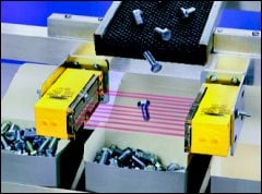
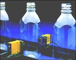
Multiplexed light screens of tightly spaced opposed-mode beams are used for on-the-fly part profiling, part ejection verification, part counting, optical safety systems, and similar applications (see Photo 2).
Retroreflective Mode Beam Patterns
A retroreflective- (or retro-) mode sensor contains both emitter and receiver circuitry. The sensor passes a light beam along a path linking the emitter, a retroflective target, and the receiver. As in
|
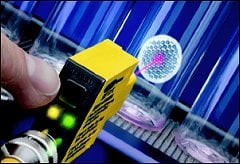
Most retroreflective targets (also called retroreflectors or retro targets) are made up of many small corner-cube prisms, each of which has three mutually perpendicular surfaces. When a light beam enters a prism, the perpendicular surfaces reflect the beam back, parallel to the entering beam. In this way, the target returns the beam to its source. A good retroreflector returns about 3000 times as much light as does a piece of white paper. This is the main reason why it is easy for a well-designed retroreflective sensor to recognize only the light returned from its retroreflector.
Beam patterns for retroreflective sensors are plotted using a standard 3 in. dia. retroreflector (see Figure 4).
 Figure 4. Beam patterns for retroreflective sensors show sensor response to a standard 3 in. dia. retroreflective target. |
Retroreflectors are available in many different sizes and with different reflective efficiencies. As logic dictates, the size of the beam pattern is proportional to the size and the reflective efficiency of the retroreflective target.
The horizontal scale is the distance from the retro sensor to the retroreflector. The vertical scale is the farthest distance on either side of the sensor's optical axis, where a retroreflector can establish a beam with the sensor.
The retro beam pattern indicates how one 3 in. dia. target will interact with multiple parallel retroreflective sensors mounted on close centers. The beam pattern also predicts whether a 3 in. dia. reflector will be detected if it is traveling past the sensor, parallel to the sensor face, or vice versa.
Most important, a retroreflective beam pattern provides an accurate depiction of the size of the active beam area a few feet or more from the sensor. It's always good practice to capture the entire emitted beam with the retroreflective target area. The pattern indicates how much reflector area is needed at any given distance when the beam size is >3 in. wide.
Proximity-Mode Beam Patterns
|
The beam pattern for a proximity-mode sensor represents the boundary within which the edge of a light-colored diffuse surface will be detected as it moves past the sensor. The target used to plot the pattern is a Kodak 90% reflectance white test card, which is about 10% more reflective than most white copy paper. The beam pattern will be smaller for materials that are less reflective and may be larger for surfaces of greater reflectivity.
The card measures 8 by 10 in. Substantially smaller objects may decrease the size of the beam pattern at long ranges. Also, the angle of incidence of the beam to a shiny surface has a pronounced effect on the size and the shape in a diffuse-mode beam pattern.
The horizontal scale is the distance from the sensor to the reflective surface. The vertical scale is the width of the active beam measured on either side of the optical axis (see Figure 5). The beam pattern for any proximity-mode sensor is equivalent to the sensor's effective beam.
 Figure 5. Beam patterns for proximity-mode photoelectric sensors are plotted using a 90% reflectance Kodak white test card. Reflectivity and surface characteristics of the object to be sensed can affect the size and shape of a proximity-mode beam pattern. |
Summary