
Introduction
In this article, the requirement of oxygen sensors in the automobiles is explained. We also discuss the principles of operation of an oxygen sensor in fulfilling its requirements.
Oxygen sensor simulation is performed using a lab feasible and low cost circuit including a 555 timer and level shifter logic in addition to testing the oxygen sensor in the lab. Simulation results of the sensor output and how the output is used to generate control signals to an Engine Control Unit (ECU) are also explained.
Oxygen Sensor
Due to rising fuel prices and global environmental concerns, the emission of harmful gases like carbon dioxide (CO2) into the atmosphere and proper engine operation, fuel efficiency of automobiles has become an important critical parameter in today's auto world. One of the equipment in automobiles critical to these issues is the oxygen sensor.
An oxygen sensor is an electronic device installed in cars to determine the proportion of oxygen present in the exhaust gas. It helps to maintain the required Air/Fuel ratio in the combustion engine for best fuel economy of the car. Normally this ratio is 14.7:1, which means that 14.7 units of air must be burnt with 1 unit of fuel for achieving maximum fuel efficiency. The maintenance of this ratio is achieved with the help of the oxygen sensor.
Combustion of fuel produces gases like Nitrogen monoxide (NO), Carbon monoxide (CO), etc. Nitrogen monoxide and Carbon monoxide are extremely harmful gases. They are not directly released to the atmosphere. These gases pass through a catalytic converter, which converts Carbon monoxide, Nitrogen monoxide to less harmful gases like Carbon dioxide and Nitrogen dioxide, respectively, which are released into the atmosphere.
With the passage of time, the efficiency of the catalytic converter decreases and it is not able to completely convert Carbon monoxide, and Nitrogen monoxide, resulting in the release of harmful gases. An oxygen sensor is employed after the catalytic converter to help overcome this problem by determining the efficiency of the catalytic converter. When the oxygen sensor indicates that the efficiency of the catalytic converter is below a certain threshold value, it indicates that the current catalytic converter should be replaced with a new one.
If the oxygen sensor fails then the ECU ends up guessing and will either consume more fuel or damage the engine.
Principle of operation of Oxygen Sensor
Oxygen sensors work on the Galvanic cell principle. It generates an output voltage signal depending on the difference between the oxygen present in the exhaust gases and the oxygen in the air.
It consists of Zirconium dioxide (sensing element), which is coated with platinum on the outside as well as the inside of the probe. The outside surface of the sensor senses the oxygen from the exhaust and the atmospheric air is made to flow through the inside of the oxygen sensor. The change in the concentration of the oxygen content on the outside and inside of the surface of the zirconium dioxide produces an output voltage.
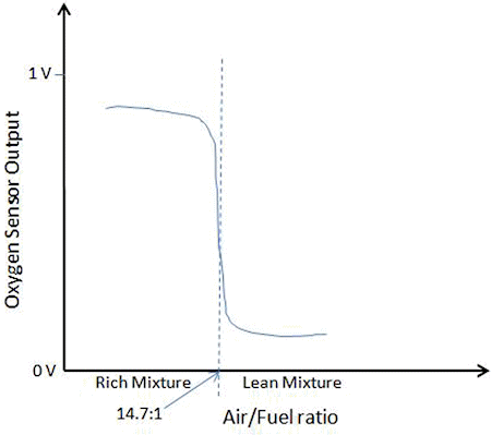
Fig. 1: Output of Oxygen Sensor with respect to Air/Fuel ratio
If a ratio of 14.7:1 of Air:Fuel is burnt, then the output of the oxygen sensor is 0.45V. If the mixture is lean i.e. air is more than the fuel in the mixture, then the exhaust will have more oxygen and the output of the oxygen Sensor will be less than 0.45V. If the mixture is rich, i.e., fuel is more than the air in the mixture, then the exhaust will have less oxygen and the output of the Oxygen Sensor will be more than 0.45V.
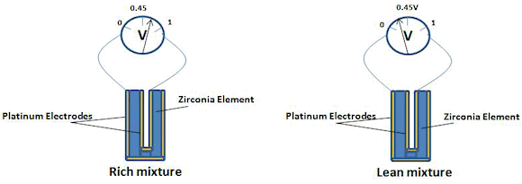
Fig. 2: Oxygen Sensor (using Zirconia) Output for Rich and Lean Mixture
In this way, depending on the output of the oxygen sensor, the ECU decides whether the mixture is lean or rich and takes appropriate control action on the subsequent stroke to achieve the 14.7:1 ratio.
1. Oxygen Sensor for Maintaining Fuel Economy
The combustion chamber burns fuel and oxygen to produce power. It turns out that the 14.7:1 ratio of air-to-fuel is required for the complete conversion of fuel. If in the combustion chamber the amount of fuel is more than the air, then the mixture is called rich mixture. Due to rich mixture there will be left some unburnt hydrocarbons in the output. This will decrease the engine efficiency and pollute the environment.
If in the combustion engine there is more air than fuel, then the mixture is called lean mixture. Due to lean mixture the performance of the engine degrades due to the burden on the engine to generate torque with less combustion. The oxygen sensor employed before the catalytic converter in the automobiles is used for maintaining the 14.7:1 air-to-fuel ratio for proper fuel economy. It senses the amount of oxygen present in the exhaust chamber and produces an output voltage that is fed to the ECU. The 14.7:1 ratio is achieved by the control action taken by the ECU. The ECU is a control unit that on the reception of a control signal from the output of the oxygen sensor takes proper action to increase or decrease either the fuel or air by acting on the control valves of the fuel and Air. In this way it works in feedback control mode to maintain the required ratio of air-to-fuel.
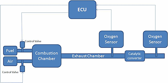
Fig. 3: ECU taking control action depending on the output of Oxygen sensor
2. Oxygen Sensor for Controlling Emission of Gases Harmful to the Atmosphere
After the combustion of fuel and air, the gases produced are CO, NO. These are harmful gases and therefore should not be released to the atmosphere. So, before these gases are released to the atmosphere, they are passed through the catalytic converter. The catalytic converter changes these harmful gases (CO, NO) into less harmful gases like CO2, NO2. But with the passage of time the efficiency of the catalytic converter is reduced, which means that it cannot completely convert NO, CO to NO2, CO2 respectively, thereby releasing some of the harmful gases to the atmosphere. The oxygen sensor employed after the catalytic converter monitors the oxygen content in the exhaust gases after they are passed through the catalytic converter and produces a voltage output. This voltage output is fed to the ECU, which determines the efficiency of the catalytic converter. If the efficiency of the catalytic converter falls below a certain threshold, the ECU generates a control signal indicating the user to change the catalytic converter.
Parameters of Oxygen Sensor:
The output voltage of the oxygen sensor varies from 0.1V to 0.8V with the frequency of 1 Hz. This output voltage changes over the life of the oxygen sensor.
Oxygen Sensor simulated using 555 Timer:
In order to test the performance of the oxygen sensor in the lab, it is difficult to create the actual application scenario where the oxygen sensor is tested using exhaust gases at high temperature. Since we can model the oxygen sensor with the help of a 555 timer and some level shifter logic, we can test the output of the oxygen sensor and any variation with the change of different variables by simulating using a circuit comprising a 555 timer and level shifter logic.
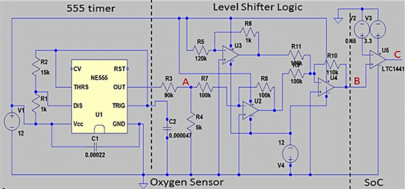
Fig. 4: Oxygen Sensor simulated using 555 Timer
Figure 4 shows how a 555 timer along with op amps can be used to create an output voltage that is similar to the output of the oxygen sensor, which is later compared with a comparator (LTC1441) to generate a control signal to the ECU.
The output of the 555 timer (point A in Fig. 5) is a pulse waveform with the amplitude varying from 0V to 600mV. This output voltage is then adjusted to 0.V to 0.77V (at point B in Fig. 5) using op amp circuits. The output of the last op amp goes to the comparator, which compares the output voltage with 0.45V. If the output of the op amp is less than 0.45V then the output of the comparator is low (0V) and if the output of the op amp is more than 0.45V then the output of the comparator is high (3.3V). The output of the comparator (at point C in Fig. 5) is fed to the ECU, which on the output of the comparator takes the appropriate control action to increase or decrease the air-to-fuel ratio by controlling the air and fuel inlet control valves.
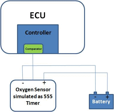
Fig. 5: Oxygen Sensor connected to ECU
Figure 5 shows the top level view of the output of the oxygen sensor connected to the ECU of the automobile.
Simulation Results
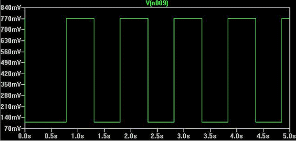
Fig. 6: Output of Oxygen Sensor
Simulation results of the output of the oxygen sensor are shown in figure 6. The output of the oxygen sensor varies from 0.1V to 0.77V with a frequency of 1 Hz.
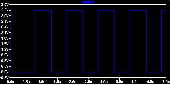
Fig 7: Output of Comparator that goes to the ECU
Simulation results of the output of the comparator are shown in figure 7. The output of the comparator goes low if the output of the oxygen sensor is less than 0.45V and goes high if the output of the oxygen sensor is more than 0.45V.
Summary
Oxygen sensors are required in automobiles for maintaining fuel economy and controlling the emission of harmful gases to the atmosphere. We can also simulate and integrate the behavior of an oxygen sensor with the help of inexpensive circuitry utilizing a 555 timer and level shifter logic.
Related Story:
Automotive Sensors
About the Authors
Prashant Goyal is Freescale Semiconductor's lead SOC validation engineer. He has 10 years of experience in SoC validation and application design in diverse fields such as automotive semiconductors plus medical and consumer electronics. He has a B.Tech degree from JSS Academy of Technical Education, Noida.
Love Gupta holds a B.E in Electronics, Instrumentation and Control from Thapar University and has been working as a System-on-Chip (SoC) validation engineer at Freescale Semiconductor since 2012. During this time, he has worked on various projects and validated multiple IPs such as 24-MHz crystal oscillators, SoC current measurements, voltage/temperature monitoring, RTC, supply ramp trials, and temperature-sensor applications.
Mohit Khajuria is a SoC validation engineer working at Freescale Semiconductor, India. He holds a B.Tech degree from IIIT, Allahabad.