
|
Accelerometers
Accelerometers are the stars of the MEMS show [1], with millions bought each year by the automotive industry. Devices with integral electronics offer readout electronics and self-test capability, and cost far less than accelerometers of decades ago. The physical mechanisms underlying MEMS accelerometers include capacitive, piezoresistive, electromagnetic, piezoelectric, ferroelectric, optical, and tunneling. The most successful types are based on capacitive transduction; the reasons are the simplicity of the sensor element itself, no requirement for exotic materials, low power consumption, and good stability over temperature. Although many capacitive transducers have a nonlinear capacitance vs. displacement characteristic, feedback is commonly used to convert the signal to a linear output. The output can be analog, digital, ratiometric to the supply voltage, or any of various types of pulse modulation. Sensors with digital output are convenient when the data must be transmitted without further noise degradation.
Among the specifications to consider when choosing an accelerometer are bandwidth, noise floor, cross-axis sensitivity, drift, linearity, dynamic range, shock survivability, and power consumption. Resonant frequency is also important because the sensor's upper useful frequency range is usually some fraction of its resonant frequency, which also determines its sensitivity and displacement per g of acceleration:
| (1) |
where:
| dg | = displacement per g |
| M and ksp | = mass and spring constant of the device |
| g | = 9.8 m/s2 |
|
|
= angular resonant frequency |
In general, the displacement of a sensing element is an essential part of the sensing process, and dg is part of the open-loop gain of the sensor, so there tends to be a strong inverse relationship between sensitivity and bandwidth for any class of sensors.
| (2) |
which causes Brownian motion of the proof mass, xB:
 |
(3) |
where:
| D | = damping coefficient of proof mass M supported by spring constant ksp |
Solving for the acceleration that generates the same motion, xB, and substituting:
 |
gives the Brownian equivalent acceleration noise in g/ Hz:
| (4) |
From Equation 4 we see that a large mass and a high Q (low damping) help achieve a low noise floor. To achieve a large mass in a micromachined sensor typically requires a wafer-thick proof mass carved out of the sensor chip. For absolute minimum noise, the damping constant must be reduced by suspending the proof mass in a vacuum from purely elastic springs. Feedback prevents the sensor from ringing at its resonant frequency.
Examples. Analog Devices manufactures a family of surface micromachined accelerometers with polysilicon as the structural and
|
The surface micromachining process developed at U.C. Berkeley in the early 1980s was at the time restricted to about two microns of structural polysilicon. In response to the stress and stress gradients that limited the size and flatness of these MEMS structures, alternative fabrication techniques were developed that yielded higher precision devices. They included thick polysilicon processes (epi-poly [4] and thick silane based deposition), the dissolved wafer process, and processes based on SOI (silicon-on-insulator) wafers.
|
High-g Accelerometers. There is a niche market for accelerometers that read out very high g's for crash tests, impacts, and missile and artillery shell launches. Charles Stark Draper Laboratory has produced an accelerometer reading out 100,000 g's. Similar devices will almost certainly be commercialized in time.
Angular Accelerometers.MEMS angular accelerometers are used primarily to compensate for angular shock and vibration in disk read/write head assemblies. These devices, while similar to linear accelerometers in terms of design, fabrication, and readout, are designed with zero pendulosity (i.e., the center of gravity is located at the centroid of the support springs), and are compliant to rotational motion yet stiff with respect to linear motion. Delphi and ST Microelectronics, manufacturers of angular accelerometers, use capacizive MEMS sensors and custom CMOS ASICs. Some of the specifications for two angular accelerometers are given in Figure 3.
| Figure 3 | ||||
| Angular Accelerometer COTS Components | ||||
| Manufacturer | Part # | BW (Hz) | Max (R/s2) | Output |
| ST Microelectronics | LIS1R02 | 30-800 | 200 | 7-bit A/D |
| Delphi | RV200L | 10-800 | 100-400 | Analog |
Geophones. Geophones can be thought of as accelerometers with very high sensitivity and no DC output requirement. With no drift or bias stability specifications, geophone design can be optimized to give the lowest noise floor. Applications include seismic sensing, machinery vibration and failure prediction, tracking and identification of vehicles or personnel, and underwater pressure gradient sensing.
Conventional geophones incorporate permanent magnets and fine wire coils to measure velocity above their fundamental resonance [6]. This is in contrast to capacitive accelerometers, which measure acceleration below their fundamental resonance.
|
One MEMS geophone that has been commercialized by Applied MEMS Inc. (see Figures 4 and 5) incorporates a three-wafer stack in which the center wafer forms the proof mass. Referring again to Equation 4, the largest mass available in most MEMS devices is the wafer itself, and a vacuum package reduces Brownian noise to a negligible level. The device is read out using a custom CMOS mixed-signal ASIC with a ![]()
![]() loop operating in force-feedback mode.
loop operating in force-feedback mode.
|
Gyroscopes
All MEMS gyroscopes take advantage of the Coriolis effect. In a reference frame rotating at angular velocity ![]() , a mass M moving with velocity v sees a force:
, a mass M moving with velocity v sees a force:
| (5) |
Many types of MEMS gyroscopes have appeared in the literature, with most falling into the categories of tuning-fork gyros, oscillating wheels, Foucault pendulums, and wine glass resonators. Conventional (non-MEMS) spinning wheel gyros are common, but levitation and rotation of a MEMS device with no springs has not yet been commercialized.
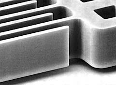
Tuning Fork Gyroscopes. Tuning fork gyros contain a pair of masses that are driven to oscillate with equal amplitude but in opposite directions. When rotated, the Coriolis force creates an orthogonal vibration that can be sensed by a variety of mechanisms. The Draper Lab gyro [7-9] shown in Figure 6 uses comb-type structures to drive the tuning fork into resonance.
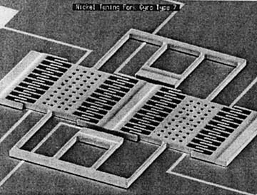 Figure 6. The first working prototype of the Draper Lab comb drive tuning fork gyro is shown here in an SEM image. Due to the superior mechanical properties of single-crrystal silicon, a much better performance was achieved using single-crystal silicon with the dissolved wafer process. |
Rotation causes the proof masses to vibrate out of plane, and this motion is sensed capacitively with a custom CMOS ASIC. The technology has been licensed to Rockwell, Boeing, Honeywell, and others.
The resonant modes of a MEMS inertial sensor are extremely important. In a gyro, there is typically a vibration mode that is driven and a second mode for output sensing. In some cases, the input and output modes are degenerate or nearly so. If the I/O modes are chosen such that they are separated by ~10%, the open-loop sensitivity will be increased due to the resonance effect. It is also critical that no other resonant modes be close to the I/O resonant frequencies.
Samsung Corp. has put a large effort into inertial sensors for automotive and consumer electronics applications. Gyroscopic stabilization of camcorders has been shown to improve picture quality, and gyroscopes are enhancing vehicular safety in multiple ways [10]. With gyros costing as little as $10.00 per sensed axis, they should soon claim a sizeable market share.
Vibrating-Wheel Gyroscopes. Many reports of vibrating-wheel gyros also have been published [4]. In this type of gyro, the wheel is driven to vibrate about its axis of symmetry, and rotation about either in-plane axis results in the wheel's tilting, a change that can be detected with capacitive electrodes under the wheel (see Figure 7).
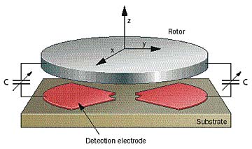 Figure 7. The vibrating wheel gyro made by Bosch Corp. [10], with capacitive sensing under the wheel, can be used to detect two in-plane rotational axes. |
It is possible to sense two axes of rotation with a single vibrating wheel. A surface micromachined polysilicon vibratingwheel gyro (see Figure 8) has been designed at the U.C. Berkeley Sensors and Actuators Center.
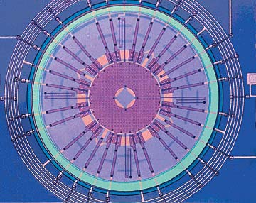 Figure 8. This polysilicon surface-micromachined vibrating wheel gyro was designed at the Berkeley Sensors and Actuators Center. The potential for combining the mechanical resonator and sense and drive electronics on a single chip permits extreme miniaturization. |
Wine Glass Resonator Gyroscopes. A third type of gyro is the wine glass resonator. Fabricated from fused silica, this device is also known as a hemispherical resonant gyro. Researchers at the University of Michigan have fabricated resonant-ring gyros in planar form [11]. In a wine glass gyro, the resonant ring is driven to resonance and the positions of the nodal points
|
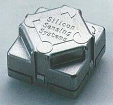
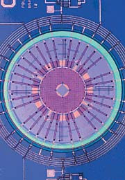
Silicon Sensing Systems, a joint venture between Sumitomo and British Aerospace, has brought to market an electromagnetically driven and sensed MEMS gyro (see Figures 9 and 10). A permanent magnet sits above the MEMS device. Current passing through the conducting legs creates a force that resonates the ring. This Coriolis-induced ring motion is detected by induced voltages as the legs cut the magnetic field.
Analog Devices has been working on MEMS gyros for many years, and has patented [12,13] several concepts based on modified tuning forks.
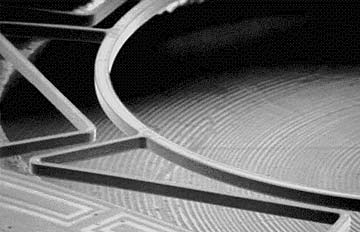 Figure 10. The resonant ring at the heart of the Silicon Sensing Systems gyro is shown here as an SEM image. Both electromagnetic drive and sensing are accomplished with a permanent magnet in the center (not shown). |
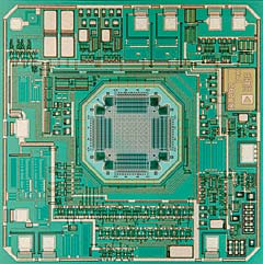
The company has recently introduced the ADXRS family of integrated angular rate-sensing gyros, in which the mass is tethered to a polysilicon frame that allows it to resonate in only one direction. Capacitive silicon sensing elements interdigitated with stationary silicon beams attached to the substrate measure the Coriolis-induced displacement of the resonating mass and its frame (see Figure 11).
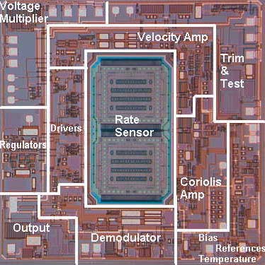 Figure 11. The iMEMS ADXRS angular rate-sensing gyro from Analog Devices integrates an angular rate sensor and signal processing electronics onto a single piece of silicon. Based on the Coriolis effect, its very low noise output makes it a good choice for GPS receivers, where critical location information is required during temporary disruptions of GPS signals. |
Foucault Pendulum Gyroscopes. These devices are based on a vibrating rod that is typically oriented out of the plane of the chip [14,15]. They are therefore challenging to build with planar fabrication tools, but recent advances in MEMS technology allow very high aspect ratio MEMS that make it possible to fabricate the pendulum without hand assembly of the rod.
Summary
MEMS inertial sensing is an established industry, with performance-to-cost rapidly improving each year. Gyroscopes and angular accelerometers are entering the marketplace and will soon make many non-MEMS components obsolete. They should also open up new applications due to their small size and weight, modest power consumption and cost, and high reliability.
References
1. N. Yazdi, F. Ayazi, and K. Najafi. Aug. 1998. "Micromachined Inertial Sensors," Proc IEEE, Vol. 86, No. 8.
2. T.B. Gabrielson. May 1993. "Mechanical-thermal noise in micromachined acoustic and vibration sensors," IEEE Trans, Electron. Devices, Vol. 40:903-909.
3. J. Bernstein et al. 8 June 1998. "Low Noise MEMS Vibration Sensor for Geophysical Applications," Proc 1998 Solid State Sensor and Actuator Workshop, Hilton Head Island, SC:55-58. Extended version also in IEEE JMEMS Dec. 1999.
4. M. Lutz et al. June 1997. "A precision yaw rate sensor in sillicon micromachining," Tech Dig 9th Intl. Conf Solid State Sensors and Actuators (Transducers '97), Chicago, IL:847-850.
5. Y. Gianchandani and K. Najafi. June 1992. "A bulk silicon dissolved wafer process for microelectromechanical systems," J Microelectromech Syst:77-85.
6. GS-14 geophone. Geospace Inc. 7334 N. Gessner Rd., Houston, TX 77040.
7. J. Bernstein et al. Feb. 1993. "A micromachined comb-drive tuning fork rate gyroscope," Proc IEEE Micro Electro Mechanical Systems Workshop (MEMS '93), Fort Lauderdale, FL:143-148.
8. J.J. Bernstein and M.S. Weinberg. 5 March 1996. U.S. Patent #5,496,436, "Comb-Drive Micromechanical Tuning Fork Gyro Fabrication Method."
9. J.J. Bernstein and M.S. Weinberg. U.S. Patent
#5,349,855, "Comb-Drive Micromechanical Tuning Fork Gyro."
10. C. Song. June 1997. "Commercial vision of silicon based inertial sensors," Tech Dig 9th Intl. Conf Solid State Sensors and Actuators.
11. M.W. Putty. March 1995. "A micromachined vibrating ring gyroscope," Ph.D. dissertation, University of Michigan, Ann Arbor, MI.
12. J. Geen. 3 June 1997. US Patent #5,635,638, "Coupling for multiple masses in a micromachined device."
13. J. Geen. 3 June 1997. U.S. Patent #5,635,640, "Micromachined device with rotationally vibrated masses."
14. J.J. Bernstein. U.S. Patent #5,203,208, "Symmetrical Micromechanical Gyroscope."
15. T.K. Tang et al. 1997. "A packaged silicon MEMS vibratory gyroscope for micro-spacecraft," Proc IEEE Micro Electro Mechanical Systems Workshop (MEMS '97), Japan:500-505.
iMEMS is a registered trademark of Analog Devices, Inc.
| ||||