

Probes
The development of probes is pushing the design of ultrasound imaging forward. With the help of COMSOL Multiphysics, Esaote has been able to investigate how to improve their performance including bandwidth and steering performance.
Medical ultrasound imaging has made great advances and provides ever more detailed diagnostic information. Thanks to new ultrasound probe technology and signal processing, it's possible to greatly increase sensitivity, bandwidth, field of view and other key parameters.
Bandwidth, in particular, is important. It provides not only greater image quality and thus diagnostic power by supporting many different frequency bands, it also means doctors need fewer probes, the name given to the handheld units placed on the body. Miniaturization makes it possible to deploy cost-effective ultrasound systems in many more applications and put them into use throughout a hospital or in specialty practices (see figure 1).
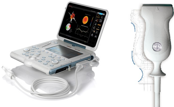
Fig. 1: The performance of ultrasonic diagnostic systems such as MyLabOne (left) depends heavily on probes placed on the skin (right).
The design of the probes is advancing. The quality of the final image is tightly related to the materials used in probe manufacturing and to the understanding of their interactions. This is exactly where a number of researchers at Esaote S.p.A. in Florence, Italy, are focusing their efforts.
Material Models
Ultrasound transducers (see figure 2) involve specialized materials, manufactured with layers as thin as 30 microns. This means that making multiple prototypes for testing is expensive. Further, we need to answer questions that can't be addressed by measurements or theoretical models. Often, we require information that the material suppliers themselves often don't have on hand, usually because they do not consider the acoustic properties of their probes at the level of detail required. You could even say that we know more about the materials than the suppliers.
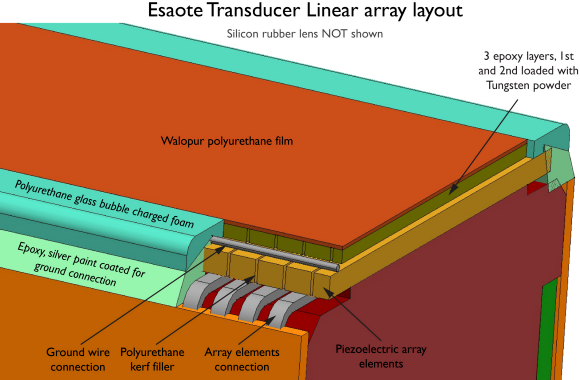
Fig. 2: A complex geometry and the use of very specialized materials make the optimization of ultrasonic probes a challenging modeling task.
With a simulation model, however, we can investigate changes in both the materials and operation. For example, COMSOL Multiphysics has made this easy with dedicated structural-acoustics interactions as well as allowing the inclusion of other coupled physics. Best of all, a simulation model provides results in one month that otherwise would take a year and many prototypes to achieve.
Among the things we are examining is how the mechanical layers in the probes affect bandwidth. We can change many aspects of the manufacturing process and easily check if the geometrical aspects, such as the thickness of the ceramic layer, are best for our purposes. Moreover, the model allows the simulation of important properties such as directivity and beam-steering capabilities. Once we found a way to optimize these properties, we then ask the manufacturer to modify its product accordingly or change some of the features of our probe design.
Our first model (see figure 3) gave us a clear picture of the material properties and made it easy to recognize the effects of each on transducer performance. It included a study of the piezoelectric material and critical elements to be considered in the transducer manufacturing stages, by simulating the electric impedance and far field pressure level (see figure 4).
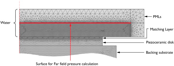
Fig. 3: Model used to simulate the final far field pressure as well as the transducer's directivity performance when the substrate and front matching layer were included.
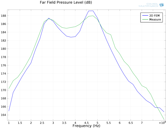
Fig. 4: Far field pressure level (dB) from the initial model (Figure 3). Experimental and model results are in good agreement, which gives us confidence in the modeling technique.
The simulations also included a matching layer in front of the disk. This layer is important because, just as with an electric system where impedances must match to transfer maximum power, the same is true for transferring acoustic power from the piezo-disk to the human body. This acoustic impedance is measured in Mrayls. In this case, the ceramic material has a high acoustic impedance (30 Mrayls), while the biological material has a low value (1.5 Mrayls).
We found that the elasticity, piezoelectric, and dielectric material properties were all equally critical in determining the behavior of the transducer, which meant that these parameters could not be simplified in a full model of the complete probe. Agreement between test measurements and simulation results were good over the entire frequency range, where the resonance and anti-resonance frequencies fit each other within an error margin of approximately 3%. This gave us confidence in the techniques we used to model this type of application. Further, by investigating the backing substrate, we also found that its parameters greatly affect the electrical impedance response.
In this first model, we used perfectly matched layers (PML) to reduce computational time and memory. For our transducers, it was important to study pressure in the far field region, and the simulated far field pressure was compared to measurements using a membrane hydrophone placed at 30 cm depth in a water tank. Biological tissue has acoustic properties very similar to water, which is often used as the standard for testing purposes. We found discrepancies of less than 5% at the maximum amplitude frequencies and differences of less than 1 dB for the corresponding amplitudes.
Modeling The Entire Probe
Having seen how well the software worked for simulating the probe materials, our next model expanded the scope to include an actual probe with its very complicated geometry and operating configuration. It simulated a wideband 5-MHz linear array probe consisting of 144 piezo elements, with a pitch of 245 microns. The transducer design was made up of a special piezocomposite material, a hard rubber backing substrate, four acoustic matching layers and a silicon rubber lens. We also started to study beam focusing and steering so we could better specify the properties of the silicon rubber lens (see figure 5).
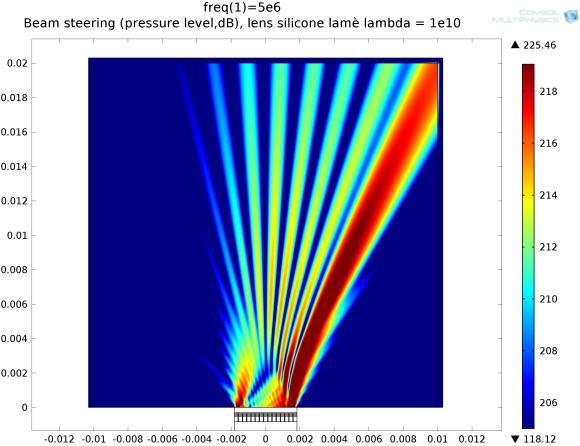
Fig. 5: COMSOL model showing how the silicon lens allows the ultrasound beam to be steered or directed.
A further investigation was to see how well a COMSOL model could be augmented by integrating it with an equivalent circuit model based on the Krimholtz, Leedom, Matthaei (KLM) model. Using the KLM method together with the electric transmission-line matching theory, it was possible to determine the values of the matching layers' acoustic impedance and thickness that give a certain, desired probe performance.
With a given input specification for the probe (sensitivity, bandwidth), it was possible to run KLM simulations and calculate the optimized thicknesses for the four matching layers (easily placed into our simulation's geometry) and the acoustic impedance (transferred to the Young's modulus and Poisson coefficient). The KLM model proved an easier, faster and more efficient tool to design the matching layer stack, which could then be implemented in COMSOL and resulted in improved designs.
About the Authors
Lorenzo Spicci has been with Esaote Biomedical in Florence, Italy, for ten years as a materials engineer & piezo/transducer designer. He earned a Laureate degree at the Università degli studi di Firenze in Florence and then a Master degree in Applied Physics at George Washington University in Washington, DC, USA.
Marco Cati joined the R&D Department of Esaote Biomedica in Florence, Italy, in 2005, and is involved in EMC design and testing activities on ultrasound and magnetic resonance devices. He graduated cum laude and with an encomium citation in electronic engineering from the University of Florence, where he later obtained his PhD in electronic engineering. Since 2001, Dr. Cati has served as a technical inspector for the Italian accreditation body ACCREDIA.
Related Stories
Adapting Acoustic Monitoring Technology to Detect Bulk Solids Flow
Pursuing Accurate, Reliable Vibration Sensing for Condition-Based Predictive Maintenance
Two approaches to Measuring Acceleration
Wearable fluid status sensor could lead to new 'vital sign'
Monitor App Integrated With Wearable Bluetooth Smart Heart Rate Sensing T-Shirt