For engineers who design motion control systems that operate in hostile environments, the biggest headache is finding hardware that will give them accurate position data on moving machine elements. Many new sensing devices simply cannot function reliably under rugged conditions. In this situation, the engineer's best option is a tried-and-true feedback sensor that has been available since the 1940s—the resolver.
Resolvers monitor the shaft angle of rotating elements (e.g., motor shafts and gears) and send the position data back to motion control systems. The device's design makes it particularly able to deal with the effects of electrical noise and vibration. For example, resolvers operate at relatively low frequency, so their components can be band limited, which reduces noise susceptibility. And because the device contains no electronics (only magnetics), it can better survive vibration and extreme temperatures.
Industrial-grade resolvers deliver accuracies of 5–10 arc-minutes, which roughly translates to 11–12 bits (Figure 1). To get the best accuracy from a resolver, you must compensate for error sources, and to do this you need to understand the resolver and signal processing elements.
Figure 1. Angular accuracy vs. digital resolution
Bit position | Degrees | Integral Degrees | Arc-Minutes | Arc-Seconds |
20 | 180 | 180 | 0 | 0 |
21 | 90 | 90 | 0 | 0 |
22 | 45 | 45 | 0 | 0 |
23 | 22.5 | 22 | 30 | 0 |
24 | 11.25 | 11 | 15 | 0 |
25 | 5.625 | 5 | 37 | 30 |
26 | 2.8125 | 2 | 48 | 45 |
27 | 1.40625 | 1
| 24 | 22.5 |
28 | 0.70313 | 0 | 42 | 11.3 |
29 | 0.35156 | 0 | 21 | 5.6 |
210 | 0.17578 | 0 | 10 | 32.8 |
211 | 0.08789 | 0 | 5 | 16.4 |
212 | 0.04395 | 0 | 2 | 38.2 |
213 | 0.02197 | 0 | 1 | 19.1 |
214 | 0.01099 | 0 | 0 | 30.6 |
215 | 0.00549 | 0 | 0 | 19.8 |
How the Resolver Tracks Position
Think of a resolver as a rotating transformer with a single primary and two secondaries. The coupling between the primary and each secondary varies as the shaft turns. Induced voltage varies from near zero to maximum and will be either in phase with the primary or 180° out of phase. Figure 2 shows a single rotation of a resolver. The reference, or input, is a constant amplitude energizing voltage. The sine and cosine signals are outputs that can be considered position feedback signals.
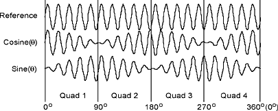 Figure 2. Resolver output as a function of angle |
You determine position by looking at the phase relationship of the three signals and then determining which quadrant the shaft is in (Figure 3).
Figure 3. Quadrant Relationship
Quadrant | Reference |
1 | In phase with sine, in phase with cosine |
2 | In phase with sine, out of phase with cosine |
3 | Out of phase with sine, out of phase with cosine |
4 | Out of phase with sine, in phase with cosine |
If you excite the resolver with a voltage represented by
| VE = Sin (ωτ) | (1) |
the position of the shaft is defined by the following trigonometric equations:
| Vsine = V Sin ( θ) Sin (ωτ) | (2) |
| Vcos = V Cos ( θ) Sin (ωτ) | (3) |
Where:
θ = the shaft angle
ωτ = the carrier
V = the peak amplitude of the voltage induced into the feedback windings of the resolver
Other than the phase relationship to the reference, the carrier plays no part in determining position. The peak voltage induced into each secondary is not the same amplitude as the reference. Resolvers usually have a voltage transformation ratio between input and output.
Modern R/D Converters
An R/D converter eases the task of converting the two analog signals to a digital value useful to modern control systems (Figure 4). A group of analog switches multiplex and weigh the feedback sine and cosine signals and compare the result to an analogous set of signals controlled by a D/A converter. The result of the comparison represents an error voltage equivalent to (θ–φ), or shaft angle minus estimated shaft angle. A demodulator removes the carrier, leaving the error signal, and an integrator scales the resulting signal. The output of the integrator controls a voltage-controlled oscillator, which in turn causes a counter string to count up or down, depending on the error polarity. A D/A converter commanded by the counter string completes the loop. This structure forms a type II servo loop, with the VCO performing the second integration.
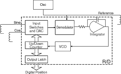 Figure 4. Simplified R/D block diagram |
If a D/R converter presented a step-position change to an R/D converter, the response would have a slight overshoot, with the settling time and bandwidth limits just like any classical servo. You must consider this characteristic when closing a resolver-conversion method in a motion control system.
The Resolver Model
Developing a simulation model for use with a tool such as SPICE will help you predict the performance of resolver/cable environments (Figure 5). Simulation can also be part of the design process if you are developing a resolver interface.
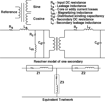 Figure 5. Detailed model and the equivalent T-network model |
Remember, the resolver can be characterized as a transformer. One significant aspect is that it has an air gap that produces a significant leakage inductance, which becomes important later when considering cables and accuracy.
The model ignores distributed capacitance because it is small for the typical frequencies used, which are in the audio range. DC resistances (Rs and Rr) are the resistance of the wire used in the windings. Leakage (Ls and Lr) inductance is significant because of the air gap. Remember, these are moving mechanical parts, and there is some clearance between rotor and stator. Rc and Lm are eddy current and magnetizing inductance losses. Taking into account the transformation ratio of primary to secondary, you can reduce the model to the equivalent T model. (see sidebar "Developing the Resolver T Model from Measured Resolver Parameters")
Error Sources
There are three main sources of potential error: cable resonance, reference phase shift, and feedback signal matching. You should also consider temperature, source impedance, and load impedance.
Cables and Resonance. You can model a twisted-pair cable as a distributed RLC network (Figure 6). Looking at the cable, the capacitance dominates, and when coupled with the resolver, a resonant situation can exist.
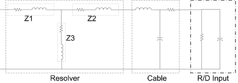 Figure 6. Twisted-pair cable modeled as a distributed RLC network |
With R/D converters, you expect the peak amplitudes of the sine and cosine feedback signals to be within a small voltage band. Again, the inductive voltage source (resolver feedback) and a capacitive load (the cable) create a natural resonant circuit. If the cable is long, the resonance will manifest itself readily, and the voltage coming back will be too great. This will lead to errors because the signals may be clipped at the quadrant boundaries.
The way around this is to reduce the excitation voltage so the feedback signals are within acceptable bounds. This can be done a number of ways. You can rotate the shaft to the zero angle position and adjust the input to get the correct value out of the cosine winding. You can also rotate the shaft to the 45° position, where both signals are the same amplitude, and adjust the input so the output is 0.707 times the required output. You can also use a trigonometric identity, which does not require angle positioning. This identity states that the sine squared plus the cosine squared is a constant.
| V = V Sin2(θ) + V Cos2(θ) | (4) |
The adjustment must be performed while the motor is standing still.
Reference Phase Shift. From the models shown earlier, you can see that there will be a delay through the resolver and cable because of the inductance. This means that the returning sine and cosine feedback signals will be out of phase with the reference and the phase shift will introduce a position error proportional to shaft speed.
There is no quick fix if this situation already exists. The solution is to have two oscillators onboard—one to excite the resolver and another to be in phase with the returning sine and cosine signals. If the oscillators are digitally based and generate an analog signal (sine wave) from a common digital clock, the phase relationship will remain the same forever. The motor should not be turning when this adjustment is performed.
Feedback Signal Matching. If the returning cable is long, you may encounter another potential error source: cable imbalance. Most resolvers—or more specifically, the feedback windings—are highly inductive, so you can characterize them as voltage sources with internal inductance. Twisted-pair cables tend to be predominantly capacitive. If the pairs are not matched, the impedance presented to the source (sine or cosine feedback) is different, producing different voltage attenuation. As a result, the returning voltages have different peak-voltage amplitudes. Because the position is derived from the ratio of the two returning signals, errors will creep in if the cable is not balanced.
Because standard cable is not closely balanced, you must compensate for the difference. The best way is to rotate the shaft slowly and monitor the peak amplitudes as the resolver rotates through the 0°, 90°, 180°, and 270° positions and adjust a variable gain amplifier to compensate. You can do this at commissioning and when the gain values are stored and restored at subsequent startups.
To do this manually, you rotate the motor through the quadrant boundaries and note the peak voltages with a true RMS meter. You can then add capacitance to the lower voltage winding to bring the peaks of the sine and cosine closer.
Output and Load Impedances. Keep energizing voltage source impedances as low as possible. Another thing to watch for is instability. The amplifier must drive a complex RLC load, so instability, or oscillation, is always possible.
Also, keep load impedances high enough to avoid pulling significant current from the resolver. Any current will generate heat in the resolver and can cause changes in performance. Remember that the feedback windings are isolated from the source and from each other, so use differential receivers for noise rejection.
Summary
Resolver inductance is the primary concern in controlling accuracy. Inductive effects can amplify small differences in voltage matching, but if you are careful, you can achieve the maximum accuracy that the resolver can offer.
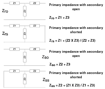
| Developing the Resolver T Model from Measured Resolver Parameters The transformer T model is developed from measured resolver characteristics for practical uses and SPICE simulations. You use measured values because they include the combined DC, AC, and magnetic properties of the resolver. The primary (rotor) and one secondary (stator) can be thought of as a four-terminal, two-port device, with an input and an output. The four parameters (Zro, Zrs, etc.) should be listed on the resolver data sheet as complex impedances (Figure 7). The goal is to find Z1, Z2, and Z3 in terms of the supplied complex impedance values listed on the data sheet or measured in the lab. Z1 and Z2 are defined in Figure 7.
When you drop actual values into this, you will get a quadratic equation, with real and imaginary components. You should be able to guess at the root. |
