
Are you sure a contact-type sensor can't handle your application? If it can, stay away from noncontact devices. They present special challenges. And don't be led in either direction solely by initial purchase and installation costs. You will need to factor in maintenance expenses as well, especially if your sensor is going to be working in a nasty environment, or if downtime would be a disaster.
Noncontact temperature sensors are available in many configurations (Figure 1), each bearing its own impressive spec sheet. These devices are called by several names, but technically they are all thermal infrared radiation thermometers. We will call them IRTs in this article. They can be portable or fixed-mount, high-end or low-end, more expensive or less so. (You might find pages 18 and 19 of your Sensors January issue helpful here, or visit www.sensorsmag.com/articles/0106/17/ for tabular comparisons of the various types.)
Figure 1. Four IR temperature sensors, Marathon MM, Raytek, www.infrared-usa.com. Modline 5, Ircon Inc., www.ircon.com. Cyclops 100, Land Instruments Intl., www.landinstruments.net. M770, Mikron, www.mikroninfrared.com. |
Finally, all IRTs operate in accordance with Planck's law of thermal emission of radiation. Most of the radiation they mea-sure lies in the IR portion of the electromagnetic spectrum.
What You'll Need to Do
There are three major challenges you will encounter when you select and use a noncontact temperature sensor:
- 1. Filling the field of view
- 2. Overcoming object transparency problems
- 3. Achieving the correct emissivity adjustment
Field of View. An object's thermal radiation "tells" the temperature of the surface, almost like a radio beacon. The difference is that in IRT measurement, the thermal radiation comes from a spot of known size on the surface. You need to capture all that radiation and not allow any to get blocked along the way.
The spot diameter at a given distance (i.e., the cross-sectional area of the "cone of vision" at a given distance) is defined by the optics of the device. Generally speaking, the farther from the sensor, the larger the spot diameter. The spot size is often expressed as a ratio such as 50:1 or 10:1. That means the minimum target spot diameter is 1 /50 or 1 /10 the distance from the sensor to the object of interest (Figure 2).
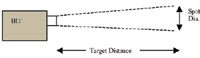 Figure 2. The spot diameter at a given distance is determined by the sensor s optics and is defined as a ratio; as a rule, the farther the target is from the sensor, the larger the spot |
If the object has a circular cross section (Figure 3), and the only view is along a diameter, make sure that the amount of severely curved surface measured is a small portion of the part viewed. Another way of saying this is that the spot diameter should be 25% or less of the curved surface's effective diameter.
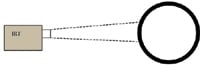 Figure 3. When you have to take a measurement on a curved surface, make sure the spot diameter is no greater than 25% of the surface s effective diamter |
Be sure to keep the sighting cone clear, too, or the detector won't receive all the radiation it needs for a valid measurement. If the site spot is bigger than the object or the sight cone is partially blocked, the apparent temperature will be lower than the true temperature.
If you can't reliably fill the spot size or keep the cone of vision unobstructed, consider getting a 2-color or ratio IRT. You will give up a little in accuracy and, possibly, response speed, and you'll pay a bit more, but these devices are made to operate where the sight path is partially blocked, the cone of vision changes, or the object moves into and out of it. They are very sensitive to emissivity ratio changes, but that's beyond the scope of this article.
Transparency Problems. Most, but not all, organic and construction materials such as bricks, wood, metals, asphalt, rocks, and minerals are opaque. Many plastics, though, are semi-transparent in the IR spectrum, so require the use of special wavebands to render them essentially opaque to the sensor. (Ircon Inc. offers some very helpful application guides to plastic and glass measurements at http://tinyurl.com/onjvf.)
Other substances that can present transparency problems include semiconductor materials (silicon, gallium arsenide), certain paints, and some optical materials such as silver chloride, sapphire, quartz, sodium chloride, germanium, and many special crystalline products.
Emissivity Correction. Don't let anyone try to tell you that this is a trivial problem. It's not, but once you break it down into the only three scenarios you're likely to encounter it becomes quite manageable:
- 1. The object of interest is at or very near the ambient temperature.
- 2. The object is hotter than ambient.
- 3. The object is cooler than ambient.
The object's optical properties (emissivity is one of them) come into play here. If your target is semi-transparent you'll probably need help; if it's opaque, you might be able to handle the emissivity correction task yourself. Let's look at an example of each case.
Case 1. If the object is about the same temperature as its surroundings and its surface is not mirror-like (specular), then its surface reflectivity makes up for emissivity and no emissivity correction is needed. To put in an emissivity correction would give a temperature reading above the true temperature.
Case 2. When the object is hotter than its surroundings, you need an emissivity correction to get an accurate reading. Emissivity can be an elusive and changing optical property, but it usually changes only if something on the surface changes, e.g., becomes burned or oxidized, or melts.
If you keep the emissivity control at 1.00, you can obtain the "radiance temperature" in this situation. Although this value will be lower than the true temperature, it is repeatable assuming that the object's emissivity, albeit unknown, does not change very much. And how much is very much? That's a good question that would take too long to answer here, but if the object looks the same visually, there's a reasonably good chance the spectral emissivity didn't change. No guarantee, just a chance.
Case 3. This is the tough one. When your target is cooler than ambient, your easiest solution is to change the location from which you take your measurement. For instance, if the object is cooler than the oven or furnace it is entering, don't try to measure its temperature at the entry, or inside while it is heating up. Move to the exit and measure as the object finishes its heating step and leaves the oven, probably hotter than its surroundings at that point.
One sort of "hidden" version of this case is when an object is illuminated by the Sun, or has a high temperature (it could still be cooler than ambient) or brightness level. You can test for these conditions by casting a temporary shadow onto the surface and aiming your IRT into that shadow.
In process lines where cooler, web-like products (e.g., metals, glass, plastics) enter a heating oven or furnace, try aiming your IRT into the "wedge" formed between the product and a roller over which it passes (Figure 4), especially if it changes directions (i.e., has a 25% or greater wrap angle). This can be a "virtual case," in that the roller surface is usually reflective and creates a mirror of the object. It is then in effect surrounded by something near its own temperature.
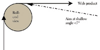 Figure 4. One solution to emissivity problems caused by your target s being cooler than ambient conditions, such as with web products, is to aim your IRT into the "wedge" formed by the roll and the product |
Parting Advice
There are many excellent noncontact temperature sensors on the market, all asking you to take them home. It's important to remember that you can't just turn them on and expect them to do the job you assign them. You have to either give them an optimum operating environment or make corrections for one that isn't.
If you would like to learn more on this subject, there are plenty of reference works, including accounts of successful application examples. One place to begin is at www.temperatures.com. There's also www.tempsensor.net. Most large public libraries and major physics and engineering libraries will have at least the latest of eight volumes of the International Symposium on Temperature: Its Measurement and Control in Science and Industry.
And for those who really can't get enough, there are the Proceedings of SPIE's ThermoSense conferences, held annually for the past 27 years.
G. Raymond Peacock, MS, can be reached at Temperatures.com Inc., Southampton, PA; 215-325-1450, [email protected], www.temperatures.com . He is also the host of the Sensors Industrial Automation Newsletter ( www.sensorsmag.com/sia).