
The geothermal heat pump offers one of the most effective ways to save energy and cut carbon dioxide emissions from buildings. In fact, the U.S. Environmental Protection Agency (EPA) says this appliance stands as one of the most energy efficient and environmentally benign of our heating, ventilation, and air conditioning options. The numbers are impressive. Installing geothermal heat pumps to their full potential nationwide would:
- Avert construction of 91–105 GW of generation capacity, which is 42%–48% of the 218 GW of new power the US will need in 2030.
- Save $33 to $38 billion annually in reduced utility bills.
Yet installations of geothermal heat pumps remain relatively uncommon. A U.S. Department of Energy (DOE) report says that to grow the market, the industry needs to present more hard data and analysis on system performance. First, the data would underscore the technology's superiority to policymakers and consumers. Second, it would enable installers to maximize the potential of the technology.
This article discusses how portable data loggers can be used to measure, record, and document the performance of geothermal heat pumps, and it also provides specific case study examples of how the technology is being applied in geothermal system monitoring applications.
Identity Crisis
Geothermal heat pumps suffer from a bit of an identity crisis. Consumers often believe, wrongly, that geothermal heat pumps are unavailable for their use because they confuse the technology with power production from geothermal geysers, which relies on steam from underground geysers and hot springs, trapped and directed to spin turbine generators in a power plant. Geothermal heat pumps (GHPs), on the other hand, can be used virtually anywhere a building sits on the ground. They do not fuel power plants but rather are appliances to heat and cool buildings or to provide hot water.
Operating Basics
Underground temperatures are cooler than air in the summer and warmer than air in the winter, remaining between 45°F and 75°F depending on latitude. Geothermal heat pumps capitalize on this temperate underground climate, using water (or an antifreeze solution) as a medium to transfer heat between the ground and the building.
A geothermal system has three main components.
- A series of underground pipes, called the geothermal loop
- A heat pump unit
- A distribution system (such as a fan and ductwork or a hydronic radiant floor)
The way the system operates depends on whether it is heating or cooling the building. In the heating cycle, the water circulates through the loop and extracts heat from the soil. The water flows to the heat pump unit inside the building and then passes through a heat exchanger. For air conditioning, the cycle is reversed, pulling heat out of the building.
Geothermal heat systems may be either open- or closed-loop. An open system often relies on well water that is drawn up to the heat exchanger. At the end of the cycle, the water goes either into a separate well, a stream, a pond, or a gulley. Closed-loop systems rely on a continuous loop of underground pipes that circulate antifreeze.
Increased Need for Data Collection
The North American geothermal market has grown dramatically in recent years. Still, the technology remains only a small part of the overall U.S. heating and cooling appliance market. According to the DOE, to help spur growth in the GHP market, the industry needs to collect data that helps track, validate, and optimize system performance. Second, installers need to collect data to customize systems geography. Specifically, the DOE recommends that installers:
- Gather "statistically valid, hard data on installed costs and energy, demand, and maintenance savings versus baseline systems in existing GHP installations in major market segments (schools, federal government, residential, etc.) by climate." The work must characterize not only the benefits to consumers, but also the reduced peak demand and improved annual load factor.
- Develop GHP "in the most economical manner" by developing "the engineering data, analysis, and tools to enable selection, design, specification, and construction of the lowest life-cycle-cost GHP infrastructure option as a function of varying conditions that may be encountered (drilling and trenching conditions, surface water availability, etc.) at the application's site and scale (building, neighborhood or community)."
Role of Data Loggers
The use of portable data loggers helps address these requirements. These battery-operated measurement devices—containing a microprocessor, memory, and sensors for measuring and recording one or more variables over time—can easily and quickly be installed at key points along the geothermal system to measure air and water temperatures, water flow, electricity consumption, and soil temperatures.
Some data loggers have internal sensors, so that measurements can be made within the logger, while others rely on external sensors that allow for monitoring at some distance from the data logger itself. The devices typically operate unattended for hours, days, or months at a time. Specialized software is used to configure the logger (select sampling intervals, synchronize logger and computer clocks, etc.) and later to graph and analyze the collected data on a PC or Mac computer.
Essentially, two types of data loggers exist: stand-alone data loggers, and Web-based monitoring systems. Stand-alone data loggers, which typically connect to a computer via a USB cable, require the user to manually offload data onto the computer, adjust configurations, and/or launch new sensors. In order to perform any of these actions, the user typically needs to travel to the site where the equipment is deployed.
Web-based systems enable users to access collected data and perform system management and control functions over the Internet without having to travel to the monitoring site. These systems may feature similar sensors, hardware, and power options as their stand-alone counterparts, but provide the convenience of integrated remote communications.
Examples of GHP Performance Monitoring
The Chewonki Foundation, a Wiscasset, Maine-based nonprofit educational institution, chose Onset's HOBO U30-ETH, a Web-enabled data logger, to use in a pilot project funded by a $20,000 grant from the Maine Public Utilities Commission. The foundation is attempting to verify claims by manufacturers that geothermal heat pumps offer energy savings of about one-third. The test is part of the state's effort to seek alternatives to Number 2 heating oil, and may lead to greater installation of geothermal heat pumps in public housing.
The foundation has installed a geothermal heat pump (Figure 1) in its 11,000 square-foot meeting center, using an existing well with a flow level of about 22 gpm. The unit serves radiant floor heating, installed in about one-third of the building. The center has attached sensors to various points on the geothermal system to measure air temperature, British Thermal Units (BTUs), kilowatt hours, and water flow rates for the 2009/2010 heating season (Figure 2).
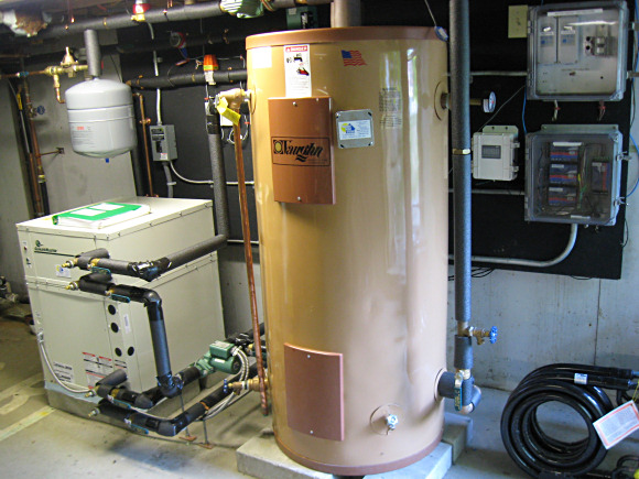 Figure 1. The geothermal heating system at the Chewonki Foundation |
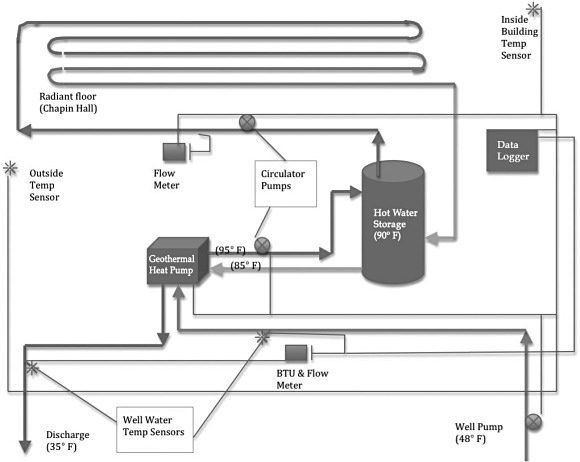 Figure 2. A diagram of the Chewonki GHP monitoring system |
Chewonki uses four temperature probes in all that send information to the data loggers. Two sensors measure the temperature of the well water entering and exiting the system, with the expectation that there will be a 10°F difference. Water should enter the open-loop system at 50°F and, after heat is extracted, exit at 40°F. The center uses the two additional sensors to measure the outside and inside air temperature.
A flowmeter connected to the well pump measures the rate at which the water enters the system; a second sensor is attached to the radiant floor heating to see how much liquid is circulating. To measure the system's kilowatt-hour consumption, the remaining sensors are attached to the heat pump, well pump, and two flow pumps, one that circulates water through the floor and another responsible for moving water from the heat pump to the hot water tank.
The foundation seeks to determine the electricity cost of the system, and how much it is paying to operate the geothermal system versus purchasing the gallons of heating oil for its previous system, normalized for changes in weather. A cost comparison requires mathematical conversion of the BTUs produced by the geothermal unit into gallons of Number 2 heating oil, a calculation the center will perform after the heating season is over. The center also is using the data to compare carbon dioxide emissions from the two systems. For every gallon of heating oil not used, the center will eliminate about 24 lb. of carbon dioxide production.
Chewonki expects data processing to be relatively straightforward because of the ease the system offers in reading and graphing data transmitted via Ethernet to the Web via HOBOlink software, which runs on an Onset-hosted server. Chewonki's data loggers are configured to offer 15 different channels of information all displayed simultaneously on a computer screen at the center. The live feed offers the center the added benefit of serving as an educational tool, in keeping with the foundation's mission. The foundation offers ecology camps and classes for middle- and high-school students, so has configured the Web page with a "public access" feature that lets faculty and students log on to see the latest measurements, as well as measurements taken over the past week and month.
Once its test year is over, Chewonki may make changes to the system to improve its performance. For example, the foundation is experimenting with keeping down geothermal costs by using a one-well system that drains the used water at the property perimeter. Given Maine's cold winters, a concern is that the water may freeze, dam, and back up. Should this happen, the center will have to invest in a second well or direct the water elsewhere onto the property by digging a new trench, which will change the length of pay back for the system.
Soil Thermal Conductivity Testing
The proper configuration of a geothermal system depends on the kind of soil on which the building sits. Major Geothermal, a 10-year-old Wheat Ridge, Colorado, company that designs and installs residential and commercial systems, uses data loggers for thermal conductivity tests of vertical closed-loop systems.
The company uses data loggers to calculate the average conductivity for the entire ground loop. It measures the normal ground temperature with data loggers then introduces heat into the circuit at known energy and flow rates and determines the resulting rise in water temperature.
The test provides an average thermal conductivity value over the entire test bore length. This value (along with the undisturbed soil temperature and empirical diffusivity data interpreted from the drill log) is used to determine the proper system design, taking into account the building's energy consumption and the heat pump performance. The value will, for example, determine the final number of bore holes required for the system, along with the minimum spacing between holes and the minimum thermal enhancement of the grout used to optimize the ground heat exchanger's performance. Major Geothermal balances the field design against the building's energy load and the required flow rates of the heat pumps. This assessment guides the designer in selecting the proper bore depth and pipe size for the field.
Depending on the constitution of the soil and moisture, the thermal conductivity value may range from a low of 0.40 BTUH/ft./°F to as high as 1.50 BTUH/ft./°F. Whether the soil is dry or wet will determine its heat capacity. Dry soil has a heat capacity of about 0.20 BTU/lb./°F of temperature change—only one-fifth the heat capacity of water. Moist soils have better heat capacities of about 0.23–0.25 BTU/lb./°F.
To conduct the test, Major Geothermal attaches two sensors to the water-filled ground loop, one on the inlet to the unit and one on the outlet going back to the ground loop. The circulation pump is activated and the average loop temperature is measured. The heating elements are switched on and the temperatures measured again. The data logger samples every 30 s for 48 hr. The company also monitors the voltage and amperage. Since the pumps are water-lubricated, the heat of the pump is added in. The company calculates voltage × amps= kWh × 3420 BTU = total BTU.
The measurements show how well the loop dissipates heat to the ground. Conductivity is described as BTU/hr.⋅ft.⋅°F. A conductivity of 0.55 may require 3180 vertical feet of tubes, while a 1.5 conductivity may require only 2110 ft. Such a variation in size can mean a nearly $10,000 difference in the cost of a 10-ton system, if the tubing is $9/vertical foot.
According to Major Geothermal it is important to determine thermal conductivity values for each building site and heat exchanger configuration. Guessing that soil conductivity is typically the same in a given region leads to incorrectly sized systems, which do not perform as efficiently and therefore create substandard energy and cost savings. The thermal conductivity test value applies only to the specific depth of the test bore. A test bore of 300 ft. may have a different value than, say, a 400 ft. hole drilled in the same area.
In some cases, a thermal conductivity test may not be cost effective, particularly for a small system. If a test is not warranted, a trained designer should size the system with premodeled data. Knowledge of the type of heat exchanger to be used, the loads and equipment serviced by the heat exchanger, and comprehension of minimum ranges of thermal conductivity values are necessary to determine whether a thermal test is warranted.
Conclusion
Geothermal heat pumps offer substantial energy and cost savings. But their benefits will only be realized through careful monitoring that documents how well they perform against other heating systems and that help installers optimize the GHP's potential. Onset data loggers offer inexpensive and highly detailed information collection that serves these ends.
HOBO and HOBOlink are registered trademarks of Onset Computer Corp.
ABOUT THE AUTHOR
Evan Lubofsky, Director of Marketing, can be reached at Onset Computer Corp., Bourne, MA; 800-564-4377, [email protected].