Introduction
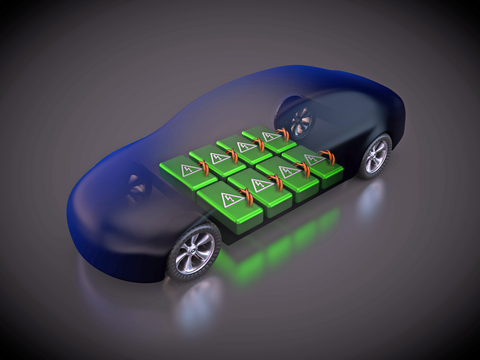
Electric vehicles are powered by huge battery banks, constructed of long strings of batteries in series (Figure 1). These battery banks, typically made up of lithium-ion (Li+) cells, can achieve operating voltages higher than 800V. However, the materials of this battery chemistry can be damaged if overcharged. Each cell voltage must be monitored and, if necessary, appropriate control methods must be applied to avoid overvoltage. Excessive cell leakage current, overvoltage, undervoltage, and extreme temperature can all lead to weaker performance or even catastrophic failure.

This article reviews the structure of a typical electric vehicle (EV) battery and highlights many concerns associated with its complexity and safety. We then introduce a novel battery management system that overcomes these concerns, allowing EV power system engineers to design with confidence.
EV Battery Structure
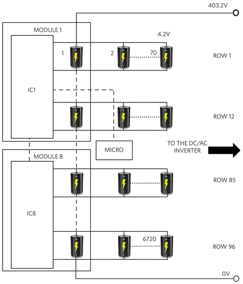
The typical EV battery depicted in Figure 2 is made of 6720 Li+ cells, managed by eight control modules. Each cell has a capacity of 3.54Ah, adding up to a total battery nominal energy storage of 100kWh (3.54Ah x 4.2V x 6720 cells). The series of 96 rows, each made of 70 cells in parallel, add up to a battery voltage of 403.2V (96 rows x 4.2V), with a capacity of 248Ah (100kWh/403.2V or 3.54Ah x 70 columns).

This allows an EV to travel 300 miles at a speed of 50mph for 6 hours before exhausting the battery. The EV motor will draw an average current of 41A (248Ah/6h).
Data Link
In the daisy-chain configuration of Figure 2, all the control modules communicate serially with a central microprocessor via IC1; isolation is required between the microprocessor and the first module, and from one module to the next. Alternatively, in an isolated controller area network (CAN) configuration, a more cumbersome solution is necessary since each module requires one microprocessor and a CAN IC, in addition to the BMS IC. The data link must reliably operate in noisy high-power battery environments, where both the high dV/dt supply noise and common-mode current injection (induced by electromagnetic fields) are present.
Cell Diagnostics
Many things can go wrong in a battery pack. Excessive current leakage, high or low voltage, and extreme temperature of the cells can all lead to weakened performance or even catastrophic failure. The manifestation of these faults varies with the battery cell configuration. In a series stack of cells, voltage variations are more readily spotted, while in parallel configurations, the leakage current becomes amplified. In a mix of series-parallel configurations, like the one in Figure 2, deviations in leakage current are more readily measured while voltage deviations induced by a single bad cell are attenuated and require measurements with a higher level of accuracy.
Cell Balancing
Li+ and lithium-polymer battery chemistries cannot be overcharged without damaging their active materials. In a string of cells in series, the state-of-charge (SoC) of each cell voltage must be monitored, and if necessary, appropriate control methods must be applied to avoid overvoltage due to overcharge. Cells in parallel tend to be self-balancing since the parallel connection holds all the cells at the same voltage preventing runaway voltage of a single cell. Accordingly, in a matrix of cells such as in Figure 2, the monitoring proceeds by a row of cells, rather than a single cell. Each module in Figure 2 contains all the electronics necessary to perform balancing by means of arrays of switches and with resistors that are connected across the cell nodes.
Cell Voltage Measurement Accuracy
The accuracy of the cell voltage measurement is important for safety reasons as well as for maximizing the battery capacity. Every millivolt of inaccuracy ultimately translates into a diminished utilization of battery capacity. Accuracy is one of the parameters that weighs heavily in the battery’s state-of-health (SoH) and SoC.
Safety Level
Automotive Safety Integrity Level (ASIL) is a risk classification scheme defined by the ISO 26262 standard. There are four levels of risk identified by the standards ASIL A through ASIL D, with the latter corresponding to the lowest level of risk. An ASIL-compliant IC is equipped with the necessary diagnostics to detect specific fault conditions.
An Integrated Solution
Cell safety, diagnostics, and balancing are all addressed by a new automotive smart sensor data acquisition IC. The MAX17843 is a programmable, high-voltage, smart data-acquisition interface with extensive features for safety with high integration and battery monitoring. The analog front-end combines a 12-channel voltage-measurement data-acquisition system with a high-voltage switch-bank input. Each of the eight modules in Figure 2 is powered by a single MAX17843. Two auxiliary analog inputs can be used to measure external thermistor components. A negative temperature coefficient (NTC) thermistor can be configured with the AUXIN analog inputs to accurately monitor module or battery-cell temperature. A thermal-overload detector disables the on-board linear regulator to protect the IC. A die-temperature measurement is also available.
Resistive Cell Balancing
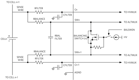
Cell balancing in the MAX17843 can be performed using any of the 12 internal cell-balancing switches to discharge cells. The cell-balancing current is limited by the external balancing resistors (RBALANCE in Figure 3) and the internal balancing switch resistance (RSW).

The high-current (up to 400mA) integrated switches greatly reduce BOM cost and increase reliability. They also enable a simpler path to higher levels of ASIL certification.
Tight Voltage Measurement Accuracy
With its high accuracy (±2mV at +25°C at 3.6V), the MAX17843 more precisely measures the battery cell voltage, which helps enhance the battery’s safety and capacity utilization (the SoC and SoH).
Daisy-Chain Communication
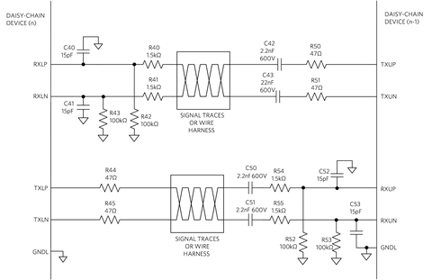
This highly integrated battery sensor incorporates a high-speed differential UART bus for robust daisy-chained serial communication, designed for maximum noise immunity. The daisy-chain method reduces cost and requires only a single isolator between the lowest module and the host. DC-blocking capacitors or transformers are used to isolate daisy-chain devices that operate at different common-mode voltages. Inexpensive capacitors can be used in the daisy chain between modules (Figure 4), which reduces system cost.

Safety Measures
The IC achieves superior safety standards by implementing safety measures for all the functional blocks. The chip has several digital and analog safety functions including:
- Monitors various pins for opens or shorts.
- Diagnoses the accuracy of the internal voltage reference using a second voltage reference.
- Detects if the HV supply has fallen below the undervoltage threshold.
- Checks for data transmission errors.
- Diagnoses if the internal die temperature monitor will generate an alert after it reaches its threshold.
The product’s compliance to ASIL D requirements is proven by a quantitative safety assessment completed according to ISO 26262 based on these and other measurements.
Conclusion
We reviewed the structure of a typical EV battery, highlighting many concerns associated with its complexity and safety. The MAX17843 12-channel, high-voltage, smart sensor data-acquisition interface addresses these concerns thanks to a high level of integration, superior safety standard compliance, high accuracy, a robust communication protocol, and the ability to implement a low-noise, cost-effective, capacitive-isolation daisy-chain communication link.
ACRONYM REFERENCES
- ASIL: Automotive safety integrity level
- CAN: Controller area network
- EV: Electric vehicle
- SoC: Battery state-of-charge is the available Ah capacity expressed as a percentage of the rated capacity.
- SoH: State-of-health. A figure of merit of the condition of the battery. Ideally a battery’s SoH starts at 100% and decreases over time and use.
- UART: Universal asynchronous transmitter receiver
About the author(s)
Tamer Kira is Director of Business Management for Automotive at Maxim Integrated. His current interests include battery and power management, specifically for electric vehicles, hybrids and plug-in hybrids. He holds a Bachelor of Science degree in Electrical Engineering.
Nazzareno (Reno) Rossetti, Ph.D. EE at Maxim Integrated, is a seasoned Analog and Power Management professional, a published author who holds several patents in the field. He holds a doctorate in Electrical Engineering from Politecnico di Torino, Italy.