
Considered by most engineers as cutting-edge or fringe technology, MEMS sensors have been embraced by the automotive industry in its quest to improve performance, reduce cost, and enhance the reliability of the family sedan. In fact, hundreds of millions of MEMS sensors have been used in automobiles over the past decade.
Many of these sensors (e.g., MEMS pressure sensors) simply replace older technologies with cheaper, more reliable devices. In contrast, MEMS inertial sensors have enabled many desirable features that are increasingly common in cars today. In this article, I'll examine automotive inertial MEMS sensor applications, describe how they work, and discuss what it is about MEMS sensors that enable or greatly improve the application. Many of the applications will be well known to you because they've become ubiquitous in automobiles. Some applications (often the most interesting) are just appearing in high-end models but are destined to become standard equipment.
Crash Sensing for Airbag Control
Crash sensing for air bag control represents the largest automotive use of inertial MEMS sensors. In this application, an accelerometer continuously measures the acceleration of the car. When this parameter goes beyond a predetermined threshold, a microcontroller computes the integral of the acceleration (i.e., the area under the curve) to determine if a large net change in velocity has occurred. If it has, the air bag is fired. The decision to fire front air bags has to be made in dozens of millisecond?; the decision to fire side air bags must be made even more quickly because the car door is closer to the occupant than the steering wheel or dashboard.
About 15 or 20 years ago, when air bags first appeared in automobiles, air bag control module makers relied on g switches (an inertial switch made up of a contact, ball, and spring housed in a cylindrical enclosure) distributed throughout the automobile. These switches don't give a lot of information about the nature of the acceleration that is being sensed. They simply provide an on/off signal telling you that the acceleration is above or below a threshold. As a result, a simple center console air bag control module requires several switches (generally three to seven) to decide if the acceleration is the result of road roughness or a crash. Worse yet—because of the reliability and long life required of their contacts—g switches are costly. Wiring them to several locations throughout the car increased their cost and reduced their reliability.
The introduction of MEMS accelerometers to air bag control modules virtually eliminated the use of g switches as the primary acceleration sensor in air bag modules. Because the MEMS accelerometer reads a continuous (analog) measurement, you can replace the g switches with one MEMS device in the center console. The resulting increase in reliability (e.g., Analog Devices' highly integrated accelerometers achieve single-digit ppm defect rates) and reduction in price of the air bag system helped bring about its near universal inclusion in cars. Better still, MEMS accelerometers can perform robust self-testing, allowing the air bag module processor to determine if the sensor's data are reliable or if the air bag module must be serviced.
MEMS accelerometers commonly control side air bags. Because the fire decision must be made quickly, there is no time to wait for the propagation of the sensor's signal through the car's chassis, so the satellite must be placed close to the air bag it conýrols. In addition, because there is virtually no crush zone between the impact and the accelerometer, the measurement range must be above the center console accelerometers. As a result, many vehicles outfitted with side air bags may add two to four more MEMS accelerometers for this function.
Front-looking crash sensors placed just behind the front bumper are being added to some models to help determine the severity of the frontal crash. The acceleration signature of the front-looking sensor is compared with that of the center console accelerometer, allowing the air bag module controller to modulate the inflation rate of the air bag to match the deceleration rate of the car. Here, too, high g range and compact size are important factors in this application.
Vehicle Dynamic Control
Vehicle dynamic control (VDC) systems help the driver regain control of the automobile when it starts to skid. If the VDC works properly, the driver may not even be aware that the system intervened.
A VDC system consists of a gyroscope, a low-g accelerometer, and wheel-speed sensors at each wheel (the wheel-speed sensors may also be used by the ABS). Wheel speed is measured, and the predicted yaw (or turn) rate of the car is compared with that measýred by the gyroscope. A low-g accelerometer is also used to determine if the car is sliding laterally. If the measured yaw rate differs from the computed yaw rate, or if lateral sliding is detected, single-wheel braking or torque reduction can be used to make the car get back in line.
Before the advent of MEMS gyroscopes and accelerometers, VDC for ordinary passenger cars was impractical. Conventional gyros and accelerometers would add thousands of dollars to the cost of the car. Indeed, conventional gyros, built with spinning masses and strain gauges, probably wouldn't be rugged enough to meet the >10-year operational requirement of the automotive market. Even the MEMS gyros are barely up to the task.
A typical MEMS gyro uses a quartz tuning fork. The vibration of the tuning fork, along with applied angular rotation (yaw rate of the car), creates Coriolis acceleration on the tuning fork. An accelerometer or strain gauge attached to the tuning fork measures the minute Coriolis force.
Signal output is proportional to tuning-fork size. To generate a strong enough output signal, the tuning fork must vibrate forcefully. You can best accomplish this with a high Q structure. Manufacturers often place the tuning fork in a vacuum to minimize mechanical damping by air around the tuning fork. High Q structures can be fairly fragile.
Because the gyro must be rigidly connected to the car to accurately measure yaw rate, the gyro often experiences shock and vibration. This mechanical noise can introduce ý signal to the Coriolis pick-off accelerometer that is several orders of magnitude higher than the tuning fork?generated Coriolis signal. Separating the signal from the noise isn't easy. Often, the shock or vibration saturates the circuitry and makes the gyro output unreliable for a short time (this explains why your VDC warning light may occasionally come on for no apparent reason).
Conventional MEMS gyros are usually bulky (100 cm3 or more is not uncommon). This is partly the result of the addition of mechanical antivibration mounts, which are incorporated to minimize sensitivity to external vibration.
New MEMS devices avoid these shortcomings, though. For example, Analog Devices' iMEMS gyro (which is in development) is 7 by 7 by 3 mm (0.15 cm3). Rather than quartz, it uses a resonating polysilicon beam structure, which creates the velocity element that produces the Coriolis force when angular rate is presented to it. At the outer edges of the polysilicon beam, orthogonal to the resonating motion, a capacitive accelerometer measures the Coriolis force. The gyro has two sets of beams in antiphase that are placed next to each other, and their outputs are read differentially, attenuating external vibration sensitivity.
Rollover Detection
Few vehicles have rollover detection systems, but automakers are rapidly adopting this feature. This is particularly true for vans, pickup trucks, and sport utility vehicles, which are more likely to roll over because of their higher center of gravity. These systems read the roll angle and roll rate of the vehicle to determine if it is tipping over. If it is, the system fires the side curtain air bags to protect the occupants.
Rollover detection systems use a gyroscope to read the roll rate. The roll rate is integrated to determine the roll angle of the vehicle, but roll rate data alone are not enough to predict if a vehicle is (or will be) rolling over. An accelerometer reading vertical acceleration (Z axis) is also required because large roll angles can be encountered in banked curves with no possibility of rollover.
Many rollover detection systems use a second accelerometer to measure lateral acceleration (Y axis). If a car is sliding sideways, it's less likely to roll over if unobstructed. But if it hits a curb or another object, the chances of a rollover increase significantly. The side crash detection accelerometer generally can't perform this task because the magnitude of acceleration when sliding sideways is close to the noise floor of the typical >100 g range used for side impact detection. A low g range, dual-axis accelerometer is best suited to reading the Y and Z axes' acceleration.
Gyros used for rollover sensing don't require the same resolution as those used in VDC systems because the roll rates are almost half an order of magnitude greater, but they must have excellent rejection of external shock and vibration. It's not unusual for a car to roll over immediately after striking another vehicle or stationary object. A gyro whose output is unreliable for a short time after a shock event is next to useless.
Antitheft Systems
One of the more popular ways to steal a car is to simply tow it away. In response to this threat, many automakers (particularly European manufacturers) are including antitheft systems incorporating tilt detection systems. Pan European specifications require accepted tilt detection systems to be capable of measuring a change in inclination of 3° over a 3 min. period (i.e., a rate of 0.016° of tilt per second).
Large electrolytic fluid tilt sensors have the required sensitivity for this application, but they fall short in many other areas. Their tilt range is limited, so it's possible to park a car at an inclination that is greater than the sensor can tolerate. In addition, fluid tilt sensors don't perform well in the widely varying automotive temperature environment. On the other hand, low g MEMS sensors are ideal in this application.
Electronic Parking Brake Systems
When you activate your parking brake, you normally pull it (or push, if pedal actuated) fairly robustly without concern for how much braking force is required. As a result, conventional parking brakes must be substantially overbuilt.
Pushing a button activates electronic parking brake systems. The system measures the inclination of the vehicle, determines how much braking force is required, and applies it. This relieves the manufacturer of the burden of having to grossly overbuild the braking system and allows such features as the automatic parking brake (once the system determines that the car is in park and at rest, it applies the parking brake).
Once again, a low-g accelerometer is used. The performance requirements are similar to those of the antitheft system. In some cases, a single sensor can provide inclination data for both systems.
Vehicle Navigation Systems
Vehicle navigation systems are rapidly becoming a standard feature in American luxury automobiles. In Japan, more than half the cars sold in 2001 were equipped with navigation systems.
A global positioning system (GPS) is a fundamental part of a navigation system, but GPS information alone is insufficient for navigation. The GPS can tell you where you are (position and altitude), but not what direction you are facing. Magnetometers (electronic compasses) are not reliable because they're confused by large ferrous metal objects close by (e.g., a truck full of scrap metal in the next lane).
Navigation systems rely on compass and GPS information when the system is first started. The direction of travel is matched up with map data to give the system more certainty regarding direction. Once initial direction is established, gyroscope information is used to determine when and how much the car has turned, until directional data can be verified by map matching.
In urban settings, it's not unusual for the GPS signal to be obscured by tall buildings or tunnels for short periods. At these times, the navigation system relies on the gyroscope for heading information and a low-g accelerometer for position informatiom. The acceleration signal is integrated twice to derive position (this technique is called dead reckoning).
The Sensor Cluster
Today, many inertial sensors are used in full-featured cars (see Figures 1 and 2).
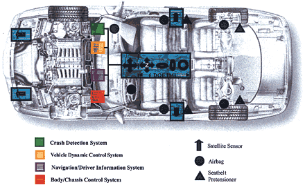 Figure 1. By using an architecture that clusters inertial MEMS sensors in the center of the automobile, fewer devices are needed to provide the information required by the various subsystems (e.g., safety and navigation). This approach is becoming the goal of many automotive OEMs. |
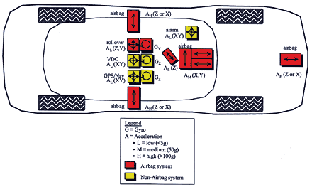 Figure 2. The number of inertial MEMS sensors used in cars is substantial and growing. Shown here are the inertial sensors used in full-featured cars today. In some cases, there are as many as 15 axes of inertial sensors (accelerometer and gyro). |
In some cases, there are as many as 15 axes of inertial sensors (accelerometer and gyro) per vehicle. But why don't manufacturers use each sensor for multiple functions? The main reason is that to date no one has had the expertise or interest to integrate all the functions in a single system. Manufacturers often deem inertial sensor signals of safety systems off limits to external functions for fear they'll lose the crash sensor signal because another subsystem (e.g., the navigation system) takes the bus down.
Nevertheless, many automotive OEMs are adopting the concept of using a cluster of inertial sensors to send information to whatever system needs it (see Figure 1). In this configuration, a six-degree-of-freedom inertial measurement unit (IMU) is located in the center of the automobile. All the inertial accessory systems (e.g., antitheft, VDC, electronic parking brake, and navigation systems) use the IMU signals, and the unit can also pass information to the air bag control unit. Separate stand-alone accelerometers are still placed at locations around the car for crash sensing. This is necessitated by the proximity-to-crash-zone demand of some of the applications.
A side benefit of the inertial sensor cluster concept is that new features can be developed at little additional cost because the inertial information is available for free. All the designer has to do is add some intelligence.
Conclusion
The inertial MEMS content of cars is substantial and growing. As the capabilities of these sensors grow, designers are finding more uses for them to improve the safety and reliability of automobiles. Today, manufacturers primarily use inertial MEMS sensors to implement safety features (e.g., air bag control), but performance and convenience applications are quickly becoming a major market.
iMEMS is a registered trademark of Analog Devices, Inc.
|