
High-intensity discharge (HID) headlights improve the safety of night driving by projecting light further down the road and increasing the time available for reaction to problems. Typical HID systems project up to 3,500 lumens, while older halogen systems produce a maximum of 2,100 lumens.
Although HID headlights improve the safety of night driving for users, they can cause glare and can (briefly) blind the driver of an oncoming vehicle on any two-lane road. This makes it more difficult for approaching drivers to identify pedestrians and other road hazards. For example, four percent of respondents to a survey cited glare as contributing to their accident [1]; the problem can often be worse for older people or anyone with a vision impairment.
Since 1998, the ECE-Regulation R48 requires the compensation of vehicle inclination caused by different loading conditions. The purpose of this regulation is to prevent the headlight glare for oncoming traffic and to ensure an optimum range of illumination. Glare countermeasures include adaptive headlights where the aim of headlights is compensated depending on the pitch of the vehicle.
This article looks at the requirements of sensor systems for measuring tilt and pitch, for those in use now and for possible future MEMS-based systems. It also includes discussion of design issues facing the sensor interface electronics.
There are three main types of headlight control: 1. Manual leveling, where the driver adapts the headlight inclination using a manual control on the instrument panel; 2. Automatic static leveling that adjusts the level of the headlights depending on the load of the vehicle while the vehicle is stationary. This is required by law in many countries; and 3. Dynamic leveling that reacts to braking and acceleration, ensuring a headlight adjustment that is always correct.
Requirements for a Headlight Leveling System
Static Leveling. Figures 1 and 2 show typical variations in pitch angle of a vehicle depending on load. The upper photograph in Figure 2 illustrates the glare that can result from inadequate headlight leveling while the lower image shows the effect of properly directed headlights. The response time required of the sensor system is slow; it can be on the order of several minutes.
Figure 1. Tilt adjustment as a function of load [2]
| Load | Tilt |
| Driver + load in trunk | 2.5° |
| Driver + 1 front and 2 rear passengers | 0.922° |
| Driver + 1 front and 1 rear passenger | 0.74° |
| Driver + 1 front passenger | –0.09° |
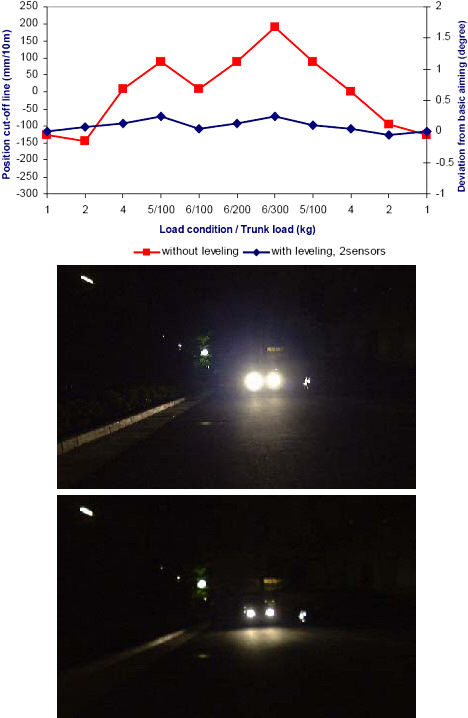 Figure 2. Effect of load on headlight direction (graph) and inadequate and appropriate headlight leveling (upper and lower photographs) |
Dynamic Leveling. While automatic static leveling requires only a very slow response, dynamic leveling needs to account for conditions such as acceleration—as much as 2 g—and braking.
Braking can cause a decrease in angle of 1.5°. This, in turn, could decrease the range of illumination from 100 m to 40 m. Accelerations can increase the angle by 2.5°, which can cause dangerous glare for other road users. For these reasons, the response time should be of the order of ≤1 s.
Existing Sensor Systems
A number of systems are available to measure the ride height of vehicles and these can be adapted to provide a measure of vehicle pitch. For instance, optical-ride sensors use transmitters and receivers to perform a triangulation measurement. This type of equipment is used for one-off testing but is too costly for use in general manufacturing. Ultrasonic time-of-flight measurements can also be used to measure ride height, but these are affected by changes in road surface, resulting in poor repeatability.
Avionic-grade inertial systems containing GPS, gyroscopes, and accelerometers can also be used, but right now these systems are too bulky and expensive for standard use in automobiles. The use of lower-cost silicon gyroscope systems is discussed later in this article.
More common systems for vehicle height and pitch measurement use suspension arms and angle sensors. The angle sensors may take the form of potentiometers or Hall effect, AMR, GMR, optical, or inductive sensors. The systems are large, use mechanical linkage elements, and are exposed to the environment under the automobile.
Simple systems normally used for static leveling use a sensor mounted on one of the axles. Dynamic leveling often uses two sensors, one mounted on each axle, to increase accuracy and response. In this case, the pitch angle is obtained using the vehicle height difference between the front and rear of the vehicle, as measured by the sensors, and knowledge of its wheelbase.
MEMS Solutions
Although MEMS devices are already used within automotive systems—MEMS accelerometers, in particular, are well established in airbag security systems—they are as yet not commonly used in production vehicles for headlight leveling. Measuring the gravity-induced change in capacitance of a MEMS accelerometer is not a trivial task and requires readout electronics with adequate sensitivity. It requires close coupling of the readout device to the sensor, which typically requires an ASIC wire-bonded in close proximity to the sensor. The readout device should also offer extremely low noise performance and minimum offset drift. The following section illustrates the performance that one might expect from a state-of-the-art readout device.
Design Calculations for Static Leveling
For two passengers seated inside a car, the resulting change in angle of a headlight beam is 0.7°. So, our goal is to detect angle changes on the order of 0.5°. If we consider a single-axis case as an example, the sensitivity of such a system varies with the angle at which it is positioned (Figure 3). Displacements about the horizontal will produce a larger gravitational component (g) in the plane of the sensor than displacements about the vertical. In our example, we take a nominal inclination of 5° and examine inclination changes around this value.
 Figure 3. Illustration of pitch and yaw angles |
The nominal projection of g onto the axis of the sensor is given by Equation 1:
| (1) |
For a change of 0.5°, we get Equation 2:
| (2) |
A typical accelerometer will show a capacitance change of 0.2 pF/g and therefore the total change in capacitance for this inclination is 1.74 fF.
The best capacitive readout devices using Σ-Δ ADCs can attain a noise floor of 3aF/![]() Hz. If we take a total bandwidth of 100 Hz, this gives 30 aF (rms) total.
Hz. If we take a total bandwidth of 100 Hz, this gives 30 aF (rms) total.
Taking the peak-peak noise value as 6.6 times the rms value, the total peak-peak noise is 0.2 fF. Using these readout devices we can obtain an angle resolution of <0.1°. However, suppliers of sensor-interface components with this capability are not common.
System Considerations for Dynamic Leveling
For dynamic measurements, using an inclinometer may not be sufficient because, as a tilt sensor, it will be inaccurate when subjected to acceleration caused by motion.
One solution is to mount an accelerometer on each axle of the vehicle. The difference between each tilt reading would give an indication of the true pitch of the vehicle. Readings from these accelerometers, coupled with a speed sensor output, could be used to estimate vehicle pitch and road gradient.
Another alternative is to measure pitch angle using a gyroscope. Established laser- or mechanical-based gyroscope technologies are used in avionic systems but can be large and expensive. Progress in the development and production of MEMS gyroscopes has seen both the size and cost of adequate-performance gyroscope systems fall to levels where large-scale use can be considered.
MEMS-based gyroscopes use the Coriolis effect to determine the angular velocity; the effect produces a coupling of energy between two vibration modes of a structure when it is rotated. A combination gyroscope/accelerometer should be mounted on the center of gravity of the test object to minimize the coupling effect of rotational acceleration into the accelerometer. As with high-performance MEMS capacitive readout electronics, gyroscope readout systems require a detailed knowledge of the interactions between the sensor and its electronics. The signal seen on the sense electrode is even smaller than that seen in tilt sensors and thus requires the use of advanced demodulation techniques. These can be performed in the analog domain or by using digital techniques. In either case, the front-end electronics need to have high precision and the lowest possible noise.
Typically, the accelerometer would be used to measure long-term tilt and the gyroscope to measure short-term rotation. An algorithm within the microcontroller/DSP would filter and mix the data to provide the tilt angle. Vehicle speed and steering angle can also be used within the algorithm. This kind of combination sensor (Figure 4) will become the trend for automotive inertial systems.
 Figure 4. Combination module |
It seems likely that a more common component in automobile navigation systems will be a device that measures acceleration in two axes as well as yaw. Yaw, the rotary motion perpendicular to pitch, measures the rotation as a car changes direction. However, pitch angle may be estimated using yaw data and lateral and longitudinal velocity (velocity in the X and Y planes), e.g., the system shown in Figure 4. This could allow information from the inertial sensor system to be used for headlight leveling [3].
Future
As combination gyroscope/accelerometer sensors decrease in cost, they may provide a more appropriate method of measuring vehicle pitch. For such systems a key factor is the role of the sensor readout interface and an understanding of the interactions between the sensor and the readout electronics. The design of the sensor interface electronics influences the final system performance. Combination sensors could enable adaptive front lighting control by changing the lighting distribution and aim while the vehicle is cornering, and monitoring and compensating (both optically and mechanically) for changing traffic, road, and meteorological conditions.
REFERENCES
1. NHTSA Docket 01-8885; Notice 01
2. Jianzhong Jiao, NAL Koito, NHTSA Workshop, July 2004
3. Hrovat, Tseng, and Brown, U.S. Patent 6714851