Measuring with Light | |
| Part 1 | |
| Part 2 | |
| Part 3 | |
| Part 4 | |
Parts 1 and 2 of this series discussed optical fibers and fiber-optic sensors, as well as their respective operating principles. To see what lies ahead for these sensors, it's useful to examine a new development in the companion world of fiber-optic communications. So, let's shift our attention to the rapidly advancing world of multigigabit, multiple optical communications channels, each with its own assigned wavelength, all propagating down a single fiber. In other words, it's time to enter the world of dense wavelength division multiplexed (DWDM) fiber-optic communications.
An Optical-Fiber Communications System
With the ever-increasing demand for more data in less time, the communications infrastructure has been undergoing significant changes over the last decade. While the link to a residence may use twisted-pair wire, coaxial cable, or even a wireless architecture, we rely on optical fiber for the primary distribution of data from one location to another.
Consider the situation shown in Figure 12, where cable TV and telephone services are delivered to a few residences. On the television side of the communications package, the cable TV company receives broadcast signals from satellites and terrestrial sources. Each analog channel is allocated 10 MHz, with roughly 40–44 channels delivered via an electron-based coaxial cable. The bandwidth associated with a few TV channels may be allocated for cable modem–delivered Internet service. 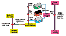
Figure 12. The standard fiber-optic communications system in the diagram shows how fiber is used by two information delivery organizations—the cable television company and the telephone company—to provide communications services into a residence.
In most instances, the telephone company delivers service to a residence via twisted-pair wire. In some areas, phone service may still be analog (~4 kHz), but in many urban/suburban areas, the service is migrating toward delivery of digital signals—potentially providing some form of digital subscriber loop (xDSL) Internet service. Although the lines of services may blur (e.g., Internet telephony over cable modems or Internet-based television over xDSL), the guiding ideas are simple—provide wider bandwidth channels efficiently and cost effectively.
Fiber-optic communications come to the rescue with channels that transmit photons, not electrons, in nonconducting glass fibers, not metallic wires. In modern fiber-optic communications systems, multiple laser sources act with each source's wavelength to transmit data at ~2 Gbps. In a dense wavelength division multiplexed (DWDM) architecture, the independent wavelengths are placed close together (0.8 nm apart) with carrier wavelengths tuned to lie within a minimum area in the optical fiber's attenuation curve (see Figure 13).
Transmitting multiple signals (e.g., telephone traffic originating in different area codes) in a DWDM scheme is similar in structure to the freq uency multiplexed scheme used in cable TV's delivery of multiple television channels. In the cable system, different channels are placed on different carrier frequencies (e.g., cable channel 2, cable channel 3, etc.), resulting in a broadband delivery of multiple channels. In the DWDM case, different collections of data/information are placed on different optical carrier frequencies, sometimes referred to as wavelengths (λ), or colors, resulting in a broadband delivery of multiple channels. For example, consider a fiber network that transports telephone/data traffic in the Northeast U.S. DWDM methodologies imply that area code 603 traffic is placed on λ1=1544 nm, area code 802 traffic is placed on λ2=1544.8 nm, and area code 617 is placed on λ3=1545.6 nm.
In a classic wavelength division multiplexing system, two data channels are
chosen to let one channel operate in each of the optical fiber's two inherent attenuation windows (i.e., 1310 and 1550 nm). A DWDM system attempts to pack many more laser wavelengths into each of the windows in the fiber attenuation curve.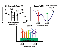
Figure 13. The dense wavelength division multiplexed (DWDM) architecture is predicated on providing wide bandwidth (2 Gbps), laser-based, optical communications signals within the so-called third window, the 1540–1565 nm range, of a fiber's attenuation curve.
The tradeoffs associated with each of the fiber windows (e.g., pulse spreading via dispersion and differing levels of signal attenuation) are frequently weighed against the costs associated with having to amplify or regenerate the signal pulses. In other words, if the overall system loss—caused by the length of the fiber and/or the number of taps into the fiber—is low, then perhaps no signal amplification is required. That implies that erbium-doped fiber amplifiers won't be used (remembering that they really work only in the 1540–1565 nm range), so you may as well place the laser signals in the 1300–1320 nm and 1540–1656 nm windows. The overall system costs are reduced, principally because signal amplification is not required.
Voila! A Metro-DWDM system is born. Alternatively, if the optical signal requires amplification, then in most instances one or more erbium-doped fiber amplifiers will be used. This restricts the DWDM operation to the 1540–1565 nm range. A long-haul DWDM system is born.
Key Components
The DWDM architecture couldn't come into being without a host of technologies moving out of the research laboratories and becoming robust, operational components. It's difficult to identify one component as the cornerstone of the system, but it is easy to identify a small set of essential components.
Stable Laser Diode Transmitters. Although you find a wide range of sem
iconductor laser designs on the market, two structures are most commonly used in lightwave communications systems: the classic Fabry-Perot (FP) structure and a distributed feedback (DFB) design (see Figure 14). The simplicity afforded by the direct current modulation of laser diodes, plus their fast rise time (~ a few picoseconds), results in a simplified system design.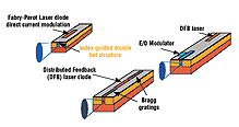
Figure 14. The dense wavelength division multiplexed laser diode transmitters come in three varieties, with varying levels of wavelength stability and cost. While a conventional Fabry-Perot design using direct current modulation is the simplest to implement, the potential exists for significant levels of wavelength variation in the laser's output. For the highest fidelity in wavelength stability, a laser diode with external modulator is typically used.
Limitations on system performance, especially in wavelength division multiplexed systems with closely spaced lasers, arise through the laser's output wavelength fluctuating as the ambient bulk temperature varies (~0.1 nm/°C) and through the laser cavity dimensional variation with applied drive current. Alternatively, an external yet integrated electro-optic modulator can be placed on a photonic structure, presenting a less sensitive transmitter for the system engineer.
Most fiber-optic transmission systems operating at data rates <2.5 Gbps use FP or DFB semiconductor lasers. Typically, they implement amplitude modulation by switching the drive current for the laser diode. The direct modulation causes the laser's wavelength to linewidth broaden (chirp) from 0.2 to 1.2 nm.
Systems with data rates >2.5 Gbps frequently use external optical modulators to lessen the linewidth broadening problem. The main disadvantage is the cost of the device and the required electrical drive electronics for the modulator.
Erbium-Doped Fiber Amplifiers. You optically excite erbium by injecting photons with wavelengths corresponding to erbium absorption peaks into the erbium doped fiber. This elevates the electrons in the erbium crystal to metastable states. Amplification occurs as a result of the fact that when photons with wavelengths in the 1550 nm range encounter the elevated erbium section of fiber, they cause stimulated emission of the elevated states. 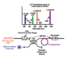
Figure 15. Although erbium can provide amplification using a number of pump wavelengths, the 980 and 1480 nm wavelengths are optimal. Inline amplification is achieved using the system architecture shown in this diagram.
For optimal inline optical amplification, the data sequence should fall in the 1540–1565 nm range. Even with the restriction on allowable wavelengths, erbium doesn't provide uniform amplification. It does, however, provide the greatest amplification efficiency.
Inline amplification is performed using the arrangement shown in Figure 15. Here amplification relies on single-mode fiber, a 2 by 2 optical coupler (a WDM), a length of erbium-doped fiber (which has been fusion spliced onto the fiber), and an optoisolator (useful but not absolutely required).
The erbium pump signal is injected into one side of the WDM, and the input data sequence is on the other side. On the output side of the WDM, both wavelengths propagate in the fiber. Typically, one output from the WDM is terminated, or it is used to illuminate a photodetector (providing a convenient measure of the power). The pump and data signal propagating down the other coupler output enters the erbium-doped section of fiber. The pump beam excites the erbium, and the data signal causes amplification through stimulated emission.
In certain cases, an optical isolator is used to prevent light from backscattering from farther down the fiber and re-entering the erbium-doped fiber. For a 10 m section of erbium-doped fiber, a pump wavelength of 980 nm will provide ~2.2 dB/mW of amplification. Overall amplification saturates around 25 dB.
Diffraction Grating Demultiplexer. Once all the wavelengths are packed into one fiber, the demodulator separates the wavelengths (see Figure 16). While there are various ways of performing this task, you can use a conventional diffraction grating. 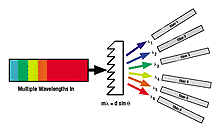
Figure 16. Because of their dispersion characteristics—sending different colors in different directions—diffraction gratings can be used to separate colors in a broadband light signal. Such a component is a ready match for use in a dense wavelength division multiplexed fiber communications system, where each wavelength is carrying unique information.
In the context of using a diffraction grating as a wavelength filter (or separator) in a fiber-optic communications system, consider the case where two colors, λ1 and λ2, are propagating down a single-mode optical fiber. The grating equation mλ = dsinθ dictates that for the fixed integer m and a fixed grating spacing d the two colors must exit the grating at different angles, θ1 and θ2. By placing single-mode fibers at these angles, the colors will each propagate down their respective output fibers.
In essence, a wavelength filter (or a demultiplexer) has just been described. By reversing the direction, this component can also be used as a wavelength combiner—in this case, directing two wavelengths into a single fiber. Note that the redirection capability of a diffraction grating causes a de crease in signal strength.
Optical Add/Drop Multiplexer. You have to be able to add and drop traffic from the communications stream if you want to be able to upgrade or even provide service to customers. In the DWDM regime, a useful add/drop multiplexer scheme uses circulators and gratings.
Here's how it works (see Figure 17). All wavelengths are presented to port 1 of the first circulator. In the drop-out portion, all wavelengths (information channels) exit the circulator at port 2. But a fiber grating has been spliced into the fiber connecting the two circulators. The grating can transmit λ1 (and perhaps 3, 4, 5, . . . n) while λ2 is reflected. λ2 then reenters circulator 1, continues around the circle, and exits the circulator at port 3. This process has just extracted a wavelength (or communications channel) from the main information artery.
Meanwhile, the other wavelengths proceed on to enter circulator 2 at its second port (port 2). These wavelengths continue around the circle and exit at port 3. Meanwhile, more communications channel data are being carried by λ2. This signal is injected into port 1 of circulator 2. It exits the circle through port 2, but once again, this wavelength encounters the fiber grating and is reflected. λ2 then goes back into circulator 2's port 2, continues a bit of the way around the circle, and emerges at port 3, just like the other wavelengths. A wavelength (or communications channel) has been added to the main information artery.
Photodetectors. Most optical detectors used in communications rely on ionization
in semiconductor material. In other words, a photon with enough energy (i.e., of the correct wavelength) will strike the surface of the semiconductor, be absorbed, and eject an electron. In a conventional PIN diode detector, the photoelectron rapidly migrates to an electrical contact, where it is swept out of the detector and electrically amplified. For a frequency response in the GHz range, this implies that a little stray capacitance can exist in the photodetector itself, which in turn implies that the detector is very small (~100 mm in diameter). A high-speed transimpedance amplifier boosts the photoelectron signal to a level at which a 0/1 decision can be made.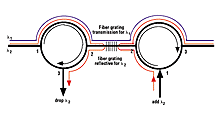
Figure 17. An optical add/drop multiplexer based on Bragg gratings and circulators resembles consecutive automobile rotaries, where different colored cars are traveling down a thoroughfare. The circulator-filter combination allows cars (or light) of only a certain color (wavelength) to exit or enter onto the thoroughfare.
Another frequently used photodetector is an avalanche photodiode detector (APD) (see Figure 18). Even though the photoelectron generation principle is essentially the same as with the PIN, an APD provides intrinsic gain, reducing the need for an additional transimpedance amplifier. But like most things in life, you don't get something for nothing. With the intrinsic gain comes the need for a power supply bias of ~200 V (essentially no current) and, more importantly, noisier performance.
Details 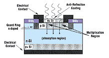
Figure 18. Shown above is a cross-sectional view of an avalanche photodiode detector (APD). The key aspects are that input photons are converted into electrons. These photoelectrons can then receive amplification in the APD, given a proper bias voltage.
Electromagnetics textbooks frequently state that "a field is a field," as described in Equation (26):
E(t)cos(ωt + φ(t)) (26)
where:
E(t) = the amplitude of the field
ω (=2πc/λ) = the frequency
φ(t) = the field's time varying phase
This is all well and good, but quantum mechanics states that there really is a difference between various types (or classes) of particles, such as fermions and bosons. While this difference can be rather cryptic—lying in the realm of stochastic processes—the essence of the difference in a communications sense is simple: Electrons repel each other, and photons have no interaction with each other. This indicates that you can pass a beam of blue light right through a beam of red light with no redirection of the photons. The elementary description of an electromagnetic wave explicitly reveals the photon field parameters that a fiber-optic communications system can vary
or modulate.
Figure 19. In an opaque optical communications system, the photons are converted into electrons, cleaned up, and then converted back to photons at each repeater. Among other things, the photonic components need to know when to make the decision that the received signal was a 0 or a 1. This implies that the components are set to a specific data rate and format.
Amplitude Modulating (AM) Communications. Most engineers would concur that an amplitude, or intensity, modulating radio is the easiest to use and/or develop because it doesn't require the sophistication necessary for tracking the frequency or phase of an optical field. Rather, the information must somehow simply modulate the Ep(t) term in Equation (27).
Ep(t)cos(ωt + θ(t)) (27)
As shown in the electromagnetic wave description, in an amplitude-based channel, the frequency and phase of the wave are not monitored. The detection portion of the receiver ignores the cos(x) term, and the detected power level from a photodetector that has been illuminated with the light field is monitored. The AM concept provides a simple method of transmitting data.
Frequency Modulating (FM) Communications. A second class of communications modulation involves mapping variation in the information into a frequency, or wavelength, modulation of the optical field. Instantly, you think of the FM vs. AM radio comparison, where FM inherently provides a larger signal variation (dynamic range) and better signal fidelity with less sensitivity to amplitude variations, but at the cost of increased receiver complexity (because the parameter of interest, ωpt, is held in the frequency term).
From an equation standpoint, the information must somehow modulate the frequency term, w, of the field equation:
E(t)cos(ωpt + θ(t)) (28)
The demodulation portion of the receiver is more involved than it is in amplitude sensing. The amplitude/intensity of the received signal is ignored. And the cosine function must be removed—the detector has to perform an inverse cosine function on the cos(x) term, canceling the cosine and leaving the frequency and phase terms. But in this case, the phase isn't monitored either, so the last term is also ignored, leaving just the frequency/wavelength term, which has been modulated by the parameter of interest. So you must track the frequency/wavelength knowing that it is varying because the information is causing it to.
Phase-Modulating Fiber-Optic Communications. In phase-modulation communications, you vary the phase term of the optical field. Detection of the variation involves an interferometric class of demoduation, which cancels any amplitude and frequency variation in the signal. As shown in Equation (29), the information modulates the phase term, θ(t).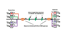
Figure 20. In contrast to an opaque optical communications system, a transparent system keeps the signal in the form of photons. Optical amplification occurs at the repeaters, but the pulse is not cleaned up. This implies that this system will operate independent of the data rate.
E(t)cos(ωpt + θ(t)) (29)
Extraction of the phase term in such a way as to allow meaningful interpretation of the information's influence on the term is beyond the scope of this article. Just as in an FM radio receiver, the mixing of fields cancels the cos(x) function. Optical/electrical bandpass filtering removes the frequency (just basically ignore the signal level, E(t)), which leaves the phase term. The remaining portion of the receiver converts the phase information into a value that can be readily handled and deciphered.
Summary. Fiber-optic communications systems can be categorized according to how they manipulate, or modulate, the light field. The intensity-, wavelength-/frequency-or phase-modulating methods can provide clear and cost-effective benefits over the more traditional types of sensors.
DWDM System Implications
The benefits of a DWDM system (and an illustration as to why the telecommunications world is setting up such systems) are best shown through an examination of a typical system implementation and its operation.
Point-to-Point DWDM Communications. The implementation benefits of a DWDM system are apparent when compared with a traditional opaque fiber communications system. As with a traditional electron-based wired communications system, the optical system requires regeneration of the signal every so often.
Early systems relied on optoelectronic repeaters to receive the signal, convert it from photons to electrons, and modify the pulse shape as needed or simply transmit a new pulsed waveform (see Figure 19). Clock recovery was performed electrically, forcing the system to operate at fixed bit rates. Such fiber-optic links may rely on electro-optical converters for the regeneration and retransmission of the data. This requires a regenerator—a receiver (photons-to-electrons), electrical retiming, reshaping, reamplification, and a laser transmitter (electrons-to-photons).
In essence, many communications engineers were using their knowledge of electron-based communications and replacing the cable plant with optical fiber. Although certainly suboptimal, this incremental movement toward true optical communications links has proven beneficial in many situations. 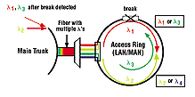
Figure 21. Faults in a dense wavelength division multiplexed implementation using a ring topology are handled by redirecting the various wavelengths.
In comparison, a transparent DWDM channel keeps the signal in the photon world (see Figure 20). In a dispersion-limited fiber-optic communications link, using erbium-doped fiber amplifiers (EDFAs) markedly changes the physical plant. Using a 980–1480 nm pump light, the EDFAs can provide enough data rate–independent amplification to increase the amplifier spacing to more than 80 km. By remaining within the optical regime, and as long as the data carrier wavelength falls within the EDFA amplification window, the need for synchronization with the various timing rates vanishes. This makes the link's bit rate and transmission protocol transparent within the dispersion limitations of the fiber. The result is a more robust communications system.
Fault-Tolerant Networks. The noninteraction of photons lets signals be transmitted both ways around fiber-optic ring topologies. The bidirectional capability provides robustness in the case of a fiber fault (i.e., when someone breaks the fiber).
Ring topologies similar to that shown in Figure 19 are frequently used to provide backup capability to the communications system. Consider the case where a lot of traffic is directed off a main fiber trunk line into an access ring (which could be serving a major metropolitan area on down to an office complex). In a wavelength division multiplexed system, wavelength switching and routing is accomplished in the following manner: In an uninterrupted ring, λl and λ2 carry all data traffic (see Figure 21). If a ring fault occurs and customers beyond the break cannot be reached byλ1, then data are switched to λ3, which travels counterclockwise in the ring. In a similar fashion, if the ring at the bottom is interrupted, data are transferred from λ2 to λ4. Even though only four wavelengths are shown in this demonstration—two for data traffic, two for backup—in reality, numerous wavelength pairs can be used.
Fiber's Dispersion Characteristics and DWDM. The use of optical amplifiers makes the already small amount of fiber transmission loss essentially meaningless. At such a point and at high bit rates (a.k.a. short pulses for each bit), all links essentially become dispersion limited. The dispersion of the fiber causes spreading of the pulses (bits) until they start to overlap and are no longer distinguishable.
You can minimize this by operating narrow linewidth lasers at the minimum dispersion wavelength of the fiber. An operator can directly modulate a DFB laser at rates up to 10 Gbps. In the presence of such a high data rate, most lasers will experience a significant variation in the output wavelength. Because of the DFB laser's internal design (in which a narrow bandwidth filter is built into the laser cavity), its output wavelength variation, ~1.2 nm, is only 1/100 of that of a typical laser diode. The linewidth can be reduced to 0.2 nm when sophisticated modulation schemes are used, but it cannot be made narrower than the modulation frequency itself (i.e., Ž10 GHz for a 10 Gbps signal).
A fiber's dispersion is proportional to the square of the bit rate. Therefore an increase from 2.5 to 10 Gbps reduces the link length to 6.25% of the original amount. In other words, the higher the data rate, the more significant the fiber's dispersion of the data bit becomes and the sooner you must reshape the pulse (hence the link length reduction).
What Does All This DWDM Stuff Provide?
From a fiber-optic-sensing perspective, the investigation of cutting-edge fiber-optic communications may not seem relevant. But nothing could be further from the truth. The reality is that whether the information being transmitted by the fiber is digital data or a sensed parameter, it is either the amplitude, frequency, or phase term of the optical field that is being modulated. To better understand how an optical communications channel works, it is best to analyze a fiber-optic sensor and vice versa.
From a market perspective, fiber-optic communications dwarfs fiber-optic sensing. Therefore, the logical question that optical engineers encounter every day is: "Can I use this fiber-optic communications component in my sensor?"
What we've just observed is that while fiber-optic sensors can operate at almost any wavelength, the world of DWDM is far more restrictive. The use of optical amplifiers—specifically erbium-doped fiber amplifiers—in single-mode, fiber-optic, long-haul DWDM systems essentially confines the wavelength window to the 1540–1565 nm band.
Deployed systems are currently operating at data rates as high as 2.5 Gbps; 10 Gbps systems are leaving the research laboratory for initial deployment. At data rates in excess of these levels, not only the optical components but also the electronics cause many problems.
Therefore many systems operate at a multiplexed 622 Mbps rate. The total amount of information capacity offered by a 16 by 622 Mbps system (9.952 Gbps) is essentially the same as a 4 by 2.5 Gbps system or even a single laser operating at 10 Gbps. A logical multiplexing step is to transmit 16 by 10 Gbps signals down the fiber (160 Gbps).
In comparison, the total peak traffic in the fiber-based public network in North America is estimated to be ~300 Gbps. The de facto standard for DWDM channel spacing has been set at 100 GHz, which corresponds to 0.8 nm. Approximately 32 separate laser signals can reside in the 25 nm EDFA window (1540–1565 nm). With each laser providing 10 Gbps, this yields an overall DWDM/EDFA communications channel of 320 Gbps.
Proprietary point-to-point systems using a 50 GHz channel spacing have further increased the bandwidth across a single optical fiber (~640 Gbps). If laser source fluctuations can be further reduced, the channel spacing limitation can be reduced. It has been estimated that the overall DWDM channel capacity available just within the 1540–1565 nm window becomes ~4 Tbps.
A standard single-mode, dispersion-shifted optical fiber is typically bundled with 20 or more other similar fibers. The multistrand cable is then installed or pulled through a cable conduit. The result is the availability of a conservatively estimated 12 Tbps of data bandwidth. This value grows to over 80 Tbps as the theoretical DWDM bandwidth is achieved across each of the fibers.
In addition to the enormous bandwidth available, the EDFA provides enough signal amplification to enable data transmission of more than 300 km without signal regeneration. When used as a simple inline amplifier, it enables dispersion-limited link lengths to have repeater spacings of ~80 km.
The reality of DWDM fiber communications is apparent when Figure 12 is reexamined. DWDM provides multiple multigigabit channels that can travel down a single fiber. Conceivably, you could allocate each residence its own wavelength. Then just think of the types of information-laden services that can be brought to your home. Yeah, but who will deliver this information—the cable company or the phone company?
Editor's Note
The figures, equations, and references in Part 3 are numbered consecutively from those in Part 1. The information in this series of articles was included in Dr. Fuhr's tutorial "Fundamentals of Fiber-Optic Sensing: Techniques, Applications, and More Applications," which was presented in the Sensors Expo Conference Program in Anaheim, CA, on May 9, 2000.
For Further Reading
While there have been thousands of technical papers and a multitude of books written about fiber-optic communications, I can recommend two texts in particular (available through www.sensorsmag.com):
Kartalopoulos, S.V. Introduction to DWDM Technology: Data in a Rainbow, IEEE Press, ISBN 0-7803-5399-4. This up-to-date description of DWDM technology presents the information in a tutorial overview, leaving many specific details for further examination.
Palais, J.C. Fiber Optic Communications, 2nd Ed., Prentice-Hall ISBN 0-13-314527-1. The work is a moderately technical general description of fiber-optic communications systems.
