Measuring with Light | |
| Part 1 | |
| Part 2 | |
| Part 3 | |
| Part 4 | |
The world of fiber-optic sensors lies at the intersection of the fiber-optic communications industry and the optoelectronics industry (which has spurred the development of such products as compact disk players and laser printers). Fiber-optic sensors take advantage of the components developed for these markets, yielding sensors with advantages over conventional electrical- and electromechanical-based sensors.
Many of these advantages stem from the fact that the fibers are made of nonconducting glass, and photons, not electrons, are used as the signal propagation element. Although systems based on semiconductor photodetectors and laser diode sources are smaller and lighter than more traditional systems, the glass's immunity to electromagnetic interference (EMI) proves to be a significant advantage. Fiber-optic sensors can be placed close to large EMI sources (e.g., power generators and electrical motors) or on structures prone to lightning strikes (e.g., bridges, towers, and aircraft). These sensors can operate in harsh environmental conditions and offer a geometric versatility that allows unobtrusive sensing.
To date, more than 60 different parameters can be measured using fiber-optic sensors. These devices can be categorized as either extrinsic (where the optical fiber acts as a transmit/receive light conduit, with signal modulation occurring outside of the fiber) or intrinsic (where an external perturbation directly interacts with the optical fiber and modulates the light signal in the fiber). Extrinsic sensors have a black box configuration because light of known parametric values enters the modulation region and upon emerging has had some feature changed (normally due to an external perturbation or environmental signal). Intrinsic sensors are all-fiber devices that measure the light modulation caused when an external perturbation changes the optical fiber's waveguide controlling boundary conditions. (See Figure 7)
The industry has found commercial uses for both classes of sensors. For instance, applications use extrinsic sensors to measure temperature, pressure, liquid level, and flow in process control and to monitor linear and angular position in aircraft fly-by-light operations. In other applications, intrinsic sensors make rotation, acceleration, strain, acoustic, pressure, and vibration measurements.
There are advantages and disadvantages to using either class of sensor. Extrinsic sensors are less sensitive, more easily multiplexed, and easier to use. They also exhibit ingress/egress connection problems (into and out of the light modulator). Whereas, intrinsic sensors are more sensitive and more difficult to shield from unwanted external perturbations. Their all-fiber design reduces or eliminates the connection problems experienced with extrinsic sensors, but they usually require more elaborate signal demodulation. From a commercial standpoint, intrinsic sensors tend to be significantly more expensive than extrinsic sensors but are more versatile for installation and are more robust. 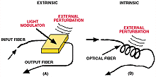
Figure 7. Fiber-optic sensing is performed either outside the fiber by an extrinsic sensor (A) or in the fiber by an intrinsic sensor (B).
Regardless of which type of sensor you choose, their sensing is similar—an environmental signal, or external perturbation, encounters the sensitized region along the fiber and modulates the light signal, varying the light's color, phase, intensity, or polarization state. The light emerges from that fiber and is measured. By comparing the modulated signal with the original light field, the device determines the measured values.
Sensing Details
The elementary description of an electromagnetic wave reveals the photon field parameters that a fiber-optic sensor may vary or modulate.
E(t) cos [ωt + φ (t)] ___________________________(21)
where:
E(t) = amplitude of the field
ω(= 2πc/λ) = frequency
φ(t) = field's time varying phase
To measure or sense a parameter of interest, the sensor design must allow an external perturbation to vary one of the terms in the field expression. The most common way of achieving this is by using an intensity modulating sensor, which functions by varying the amplitude. Alternatively, you can modulate the frequency or the wavelength of the light by using a frequency or a wavelength modulating sensor (or simply a color sensor). Modulation of the phase of the light field may prove a bit more difficult because it lies within the cosine term. Therefore, if you use such a sensor, you have to perform an inverse cosine to make the entire phase angle (frequency and phase) available. You then have to perform frequency tracking or frequency canceling, such as those used in heterodyne applications, to isolate the f(t) term. Another type of modulation uses the polarization characteristics of the light field, yielding a polarization-based sensor.
Amplitude- (or Intensity-) Based Sensors
Most engineers would agree that an amplitude, or intensity, modulating sensor is the easiest to use or develop because it doesn't require the sophistication necessary for tracking the frequency and/or the phase of an optical field. Rather, the parameter of interest must simply modulate the E(t) term of the field equation.
![]()
As shown in the EM wave description, in an amplitude-based sensor, the frequency and phase of the wave are not monitored. In other words, the detection portion of the sensor ignores the cos(x) term, and the detected power level from a photodetector that has been illuminated with the light field is monitored. You can do this in various ways, ranging from simple light interruption/reflection on/off sensors and microswitches to microbending of the fiber to obtain pressure, temperature, or another parameter of interest.
The adage "you don't get something for nothing" seems to apply here, because the ease with which intensity-based sensors perform implies that they lack the measurement sensitivity afforded by the other sensing methods. Intensity-based sensors are easy to design and are similar in concept to AM radio, but they frequently aren't as sensitive as other fiber-optic sensors that use the second term in Equation 22.
That point notwithstanding, intensity-based fiber-optic sensors—particularly those using some form of self-referencing to account for potential light source signal fluctuations—are commercially available. For example, the simplicity of intensity-based sensing lies at the heart of SUNX Corporation's (West Des Moines, Iowa) FX series fiber-optic sensors. The FX provides a controlled intensity signal that you couple into a multimode fiber. Another return fiber is attached to the receiver section of the unit. The FX monitors the intensity of the return signal and illuminates LED indicators, depending on the signal level. In this sense, the device can serve as a simple alarm circuit in such applications as presence detection or examination of a part to see if it has been electroplated.
Frequency- (or Wavelength-) Varying Sensors
This class of sensor maps variations in the parameter of interest into a frequency, or wavelength, modulation (change) of the optical field. This scheme is analogous to the FM vs. AM radio comparison, where FM inherently provides greater signal variation (dynamic range) and better signal fidelity, with less sensitivity to amplitude variations, but at the cost of increased receiver complexity (because the parameter of interest is held in the frequency term).
From an equation standpoint, the parameter of interest must modulate the frequency term, w, of the field equation.
![]()
The detection portion of the sensor is a bit more involved than that which is in an amplitude-sensing device. In the first place, the amplitude/intensity of the received signal is ignored. And the cosine function must be removed (i.e., the detector has to perform an inverse cosine function on the cos(x) term, canceling the cosine but leaving the frequency and phase terms). In this case, the phase isn't monitored either, so the last term is also ignored, leaving just the frequency/wavelength term, which has been modulated by the parameter of interest. The bottom line: Track the frequency/wavelength knowing that the parameter of interest is causing it to vary. Typically, spectral analysis is performed on the received light to see if it has changed (been modulated). If it has changed, then based on system characteristics, the parameter of interest can be discerned. 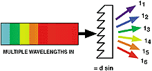
Figure 8. Diffraction gratings, like prisms, force light of different colors to be directed into different angles. Alternatively, if light of different colors enters the grating at the correct angles, all the colors will emerge from the grating traveling in the same direction. This provides an easy and passive method of combining/splitting wavelengths.
An example of such a sensor is a fiber-optic Bragg grating strain sensor, which varies the center frequency of a notch filter through which a broadband light field is transmitted. This type of grating is so important, and its use is so widespread in the sensing and communications arena, that it is worth examining in more detail. But before we examine inline fiber-optic Bragg gratings, let's review the general principles behind diffraction gratings.
Diffraction gratings separate light of different wavelengths by directing individual colors into different wavelengths. A traditional description of how this is done relies on the fact that portions of the input light field travel through glass while remaining portions of the phase front travel faster through the air. This causes a variation in the phase front, resulting in the different colors emerging from the grating at different angles.
The guiding equation is simply:
mλ = d sin θ (24)
where:
m = an integer (e.g., –3, –2, –1, 0, 1, 2, 3)
λ = wavelength of the light interacting with the grating
d = physical spacing between the lines of the grating
θ = angle at which the light of wavelength l will emerge from the grating
With a light field composed of many colors (wavelengths), each wavelength will emerge from the grating at a different angle (see Figure 8).
This describes the operation of a phase-modulating grating, but there
are also amplitude-modulating gratings. These can be written into an optical fiber, causing the angular dispersion of the wavelengths that make up the optical field. This technique is used in Bragg gratings that have been written into single-mode optical fiber.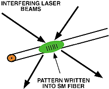
Figure 9. It's possible to write a diffraction grating into the core of a single-mode fiber. The most common fabrication procedure for such gratings involves generating a high-energy, light-dark diffraction pattern using laser(s) whose output wavelength corresponds to an absorption band of the germanium-doped singlemode fiber. The pattern essentially damages the core by locally changing the index of refraction in the high-intensity dark band of the fiber. The spacing between the pattern's dark (or light) bands is called the grating period.
One of the most critical parameters measured for structural integrity monitoring is local strain. To make these measurements, engineers commonly use conventional electrical strain gauges. These devices are relatively inexpensive and easy to attach to the structural member of interest, but they don't provide long-term (>1–2 years) monitoring primarily because of the debonding of the electrical leads from the strain rosette.
An alternative is to make the measurements with fiber-optic sensors. Optical fibers are all-dielectric (glass) and provide an easy method of multiplexing many sensors onto single-fiber leads. Research groups have examined fiber-optic strain sensors based on changing the guided light field via polarimetric [1], interferometric [2], and/or intensity variations through the use of elliptical-core fiber [3].
In the last few years, one fiber-optic strain sensor has moved ahead of the other designs because of its ease of use. That sensor—which has been dubbed a fiber Bragg grating sensor (FBGS) [4] or a Bragg intracore grating (BIG) [5]—provides the flexibilities and capabilities associated with optical fibers. The device achieves its functionality by changing the color of the light field in the fiber (wavelength modulation). In most instances, wavelength, or color, modulation is a superior parameter encoding scheme because the light source's color tends to change (or drift) much more slowly than its other parameters (e.g., intensity, phase, and polarization).
In an FBGS, a periodic variation of the fiber core's index of refraction is written into the core by high-power lasers (see Figure 9). Frequently, this requires the removal of the fiber's coating, exposure of the core to a bright light field, then recoating the fiber with polyimide to restore its durability. These steps reduce the fiber's structural strength by at least a factor of 4 [6]. The result is a tuned optical filter. The FBGS's tuning range is roughly 400–2000 nm, with a typical bandwidth of 0.1 nm in the 1300 nm band [7]. Such devices are commercially available from the 3M company (Telecom Systems Div., Austin, Texas). 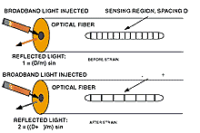
Figure 10. Strain sensing using fiber-optic Bragg gratings may be thought of as analogous to playing an accordian. In an accordian, the tone coming from the instrument changes as it expands and contracts. In the Bragg grating case, the grating was initially fabricated with a certain grating period, which means that when broadband light is injected into the fiber, only a certain wavelength, corresponding to the period, is reflected. When the grating is strained (or stretched like an accordian), the period changes, causing the color of the reflected light to change. Strain sensing happens by monitoring the color of the light being reflected—a color change indicates a certain strain level.
Sensing with an FBGS requires a broadband light source to be coupled into the fiber. The FBGS simply reflects (or filters out) the color corresponding to the grating spacing. As the fiber is strained, the grating spacing varies, causing a different color to be reflected (see Figure 10). (This is similar to an accordian, where the output tone changes as the accordian is stretched and compressed.) The response of a typical FBGS operating in the 1300 nm range yields a wavelength variation of ~1 nm/1000 mstrains. The wavelength strain sensitivity of a 1.55 mm Bragg grating is 1.15 pm/ mstrain, and its temperature sensitivity is 1.3 pm/°C [8].
Fiber-optic Bragg grating sensors (such as those sold by Blue Road Research, Troutdale, Oregon) can be purchased as a bare fiber or as a unit that combines the fiber with receiver components that extract the amount of wavelength variation for you.
Polarization Modulating Fiber-Optic Sensing
You can subdivide the electrical field of an EM wave into the amount of the field along one linear axis and the amount of the field along another linear axis that is orthogonal to the first axis. The resulting two components are referred to as perpendicular and parallel polarizations (they are sometimes called other things, but the notion is the same).
Polarization sensing can be thought of as a subclass of intensity sensing—the sensor somehow manipulates (rotates) the optical field's polarization state and uses an optical analyzer to determine the amount of rotation that the field has undergone. Knowledge of the type of optical arrangement then leads to an extraction of the parameter of interest from the amount of field rotation. 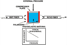
Figure 11. In an extrinsic fiber-optic pressure sensor based on polarization, pressure is applied to a plate that compresses a compliant photoelastic material. Polarized light is sent into the photoelastic material, which then rotates the polarization state of the light as the pressure changes. Another bulk polarizer (when used in this configuration it is called an analyzer) only transmits light of a certain polarization rotation. The sensor works in the following manner: with no pressure applied, there is no polarization rotation, hence the maximum field intensity emerges from the analyzer. As the pressure increases, more and more polarization rotation happens, resulting in decreasing intensity emerging from the analyzer.
An example of a polarization-based fiber-optic sensor is shown in Figure 11. In this extrinsic pressure sensor, the input light field has intensity in both axes (i.e., it's randomly polarized). The polarizer turns the input into linearly polarized light and lets only light in one orientation pass through. Next, the light passes through a photoelastic material that rotates the light in proportion to the pressure applied to the material. The output from the photoelastic material passes through another polarizer, which is in the same orientation as the first polarizer. If there is no pressure on the photoelastic material, the field is not rotated, and all the light that emerged from the first polarizer will pass through the second polarizer (in this configuration, the second polarizer is frequently referred to as an analyzer). The light is then coupled back into a length of multimode fiber (there is no concern about dispersion). The light field finally illuminates a photodetector where the intensity of the signal is monitored. Variations are assumed to be due to changes in pressure on the photoelastic material.
Engineers and scientists have devoted significant effort to the development of polarization-based sensors. This effort—plus fiber-optic communications research—has influenced the development of polarization-maintaining optical fibers. Only one polarization state will propagate in fiber. Therefore, in certain fiber-optic sensors, the bulk device polarizer and analyzer are being replaced by lengths of this type of fiber. Although the cost of the fiber is significantly higher than standard telecommunications-grade fiber, it brings design freedom to sensor developers.
Phase-Modulating Fiber-Optic Sensing
Phase-modulation sensing involves the variation of the phase term of the optical field. Detection of this parameter requires interferometric demoduation, which cancels amplitude and frequency variations in the signal. From an equation standpoint, the parameter of interest modulates the phase term.
![]()
This class of sensors has proven to be quite sensitive and idiosyncratic. Nevertheless, manufacturers have developed and demonstrated elegant schemes and sensors using the technology.
One method of signal demodulation is to interferometrically combine the current laser signal with the return signal from the sensing location (please understand that there is a wide variety of methods used to do this). As in an FM radio receiver, the mixing of fields cancels the cos(x) function. Optical/electrical bandpass filtering removes the frequency—just basically ignore the signal level, E(t)—which leaves the phase term. The remaining portion of the receiver then converts the phase information into a value that can be handled and deciphered.
Strain sensors based on Mach-Zehnder techniques or low coherence phenomena are commercially available (see Reference 1). In these instances, it's worth noting that just about anything can modify the phase of a signal. This implies that in certain instances extreme measures must be taken to isolate the sensing segment from other potentially confounding variables and to let only the parameter of interest modify the signal's phase.
For an example of a robust sensor that allows the measurement of the deformation of a large civil structure, consider the SOFO sensor manufactured by Smartec, SA (Lugano, Switzerland). This sensor is attached to a reinforcing bar in a bridge deck. Readout of the deformation information on the structure occurs through a portable sensor interrogation and interpretation unit.
Summary
Fiber-optic sensors range in sophistication, expense, and ease of use from simple intensity-modulating schemes to complex and sensitive phase-modulating sensors. In many cases, the length of the sensing region—typically referred to as sensor gauge length—is small, but what seems like an infinitely long fiber is used as the light pipe to get the signal to and from the sensing location.
Extraction of the parameter of interest runs the gamut from being a simple exercise in having a photodetector attached to a voltmeter to complicated (and expensive) spectroscopic analysis of the light in the fiber. Regardless of the complexity or lack thereof, in certain situations, particularly those associated with a hazardous or electromagnetically noisy environment, these photon-based sensors provide measurements simply not achievable by any other means. Installations of fiber-optic sensors have even begun appearing in the civil engineering domain, a true testament to the usefulness and robust nature of these sensors.
Over the course of the past two decades, development of fiber-optic sensors has led to devices and systems that can measure more than 60 different parameters. Perhaps even more noteworthy is the fact that commercially available fiber-optic sensors are increasing in frequency and in actual deployment. It is a vibrant field with clear advantages over electron-based sensors in certain applications. Fiber-optic sensors should be added to the repertoire of all individuals who use sensors to solve problems.
Editor's Note:
The figures, equations, and references in Part 2 are numbered consecutively from those in Part 1. The information in this series of articles will be included in Dr. Fuhr's tutorial "Fundamentals of Fiber-Optic Sensing: Techniques, Applications, and More Applications," which will be presented in the Sensors Expo Conference Program in Anaheim, CA, on May 9, 2000.
References
1. W. Morey, G. Meltz, and W. Glenn. 1989. "Fiber-Optic Bragg Grating Sensors," Proc SPIE, 1169:98-107.
2. J. Dunphy, G. Meltz, and W. Morey. 1995. "Optical Fiber Bragg Grating Sensors: A Candidate for Smart Structure Applications," Fiber Optic Smart Structures, John Wiley.
3. K. Hill, Y. Fujii, D. Johnson, and B. Kawasaki. 1978. "Photosensitivity in Optical Fiber Waveguides: Application to Reflection Filter Fabrication," Appl. Phys. Lett., 32:647-649.
4. J. Dunphy, G. Meltz, F. Lamm, and W. Morey. 1991. "Fiber-Optic Strain Sensor Multifunction, Distributed Optical-Fiber Sensor for Composite Cure and Response Monitoring," Proc SPIE, 1370:116-118.
5. W. Morey, J. Dunphy, and G. Meltz. 1991. "Multiplexed Fiber Bragg Grating Sensors," Proc SPIE, 1586:216-224.
6. P. Fuhr, D. Huston, T. Ambrose, and D. Barker. May 1995. "Embedded Sensor Results from the Winooski One Hydroelectric Dam," Association of State Dam Safety Officials (ASDSO) Newsletter, Vol. 10, No. 3.
7. G. Pitt. 1990. "Optical Fiber Sensors," Fiber Optics Handbook, McGraw-Hill, New York.
8. M. Ramsey. 1990. "Fiber Optic Cables," Fiber Optics Handbook, McGraw-Hill, NY.