
The U.S. Army uses parachute insertions of personnel and equipment to defend the countrys interests. However, the forces that determine whether or not the people and matériel arrive safely and intact on the drop zone are imperfectly understood. While some measurement devices and methodologies have been developed over the past 50 years, none has proved completely satisfactory.

Paratroopers descend to the ground from a USAF C-141 aircraft during a daylight mass tactical jump. In combat operations, airborne assaults are almost always at night. The smaller objects beneath two of the jumpers are rucksacks containing much of the equipment they will need on the ground. The paratrooper on the left is also accompanied by a weapon in its carrying case.
In 1998, the U.S. Armys Airborne and Special Operations Test Directorate asked scientists at the Oak Ridge National Laboratory to undertake a study to determine the dynamics of inclination. The initial study has been completed, but the challenge still stands to definitively measure all the aspects of inclination by building an affordable, accurate, and robust inclinometer.
What Is Inclination and Why Is It So Tough to Measure?
Measuring the inclination of a body is an ill-defined problem in the general case. First, inclination is a relative notion that presupposes both a well-defined axis in the body and an axis of reference external to and independent of the body and its motion (see Figure 1). The local direction of the gravitational field is normally taken as the reference axis, while a major symmetry axis or the principal axis of inertia is taken as the body axis (see Figure 2). Inclination is the angle between these two directions (see Figure 3). The direction of the inclination must likewise be referenced to absolute external coordinates.
Second, inclination is a static notion that, when extended to an arbitrary dynamic situation, leads to ambiguities of both direction and magnitude. So there is in reality an inclination definable for each of the three principal axes of inertia of the (generalized) body in question, and these inclinations are dependent on the local axis of reference, which may be changing as well.
Consider, for example, a body in free fall. There is no way to define or establish by physical measurements made within or on the body what the direction of the local gravitational field might be. The only way to determine inclination in such a case is to make measurements external to the body by an optical flow of readily identifiable features, say from a videotape of the fall, and transfer the reference axis as known from the vantage point of the video camera to the body in question. The dynamics of the inclination then become a history of the relationship of the identified and tracked identification marks.
Figure 1. Some objects, such as spheres, have no natural axis of orientation. Others have multiple candidate axes from which one must choose for the measurement. Selection of the designated 0º inclination is usually based on the payload.
Figure 2. By definition, the load on a wagon is at 0º inclination when the principal axis is perpendicular to the gravitational field.
Figure 3. Position 1 represents 0º inclination; Position 2 is 45º inclination, with inclination measured as a deviation from the designated 0º position.
In the ideal case, the orientation of a body is specified in an absolute system of coordinates. Any change in the orientation with respect to these external coordinates can be represented by an inclination (deviation) of so many degrees from the local gravitational field as defined and measured in the absolute coordinate system. Ambiguities in interpreting such a scalar number can be re solved by defining a set of three Euler angles for the body with respect to the absolute coordinates, with an ultimate interpretation as so many degrees deviation from the (externally defined) vertical, say in a north by northeast direction.
It is possible, in principle, to maintain the full orientation history of a rigid body using inertial methods alone. However, since establishment of the reference axis by meas urements made on the body cannot be guaranteed valid, this history must be maintained from some initial point where the two coordinate systems are known to be in some definite registration. In practice, each method of on-body measurement is a variation on inertial sensing (accelerometers, gyroscopic devices, vibrating reed, etc.) and has a vulnerability depending on its particular construction. Generically, any inertial sensor detects motion or a force on some dynamic element such as a point mass about some axis or center of motion.
It is thus possible to write a generic equation of motion for the extended body representing the sensor. In all cases, the dynamics are those of an expression for the motion (vector equation equating the applied external forces to the first derivative of the momentum) of the objects center of mass, and another (tensor) equation equating the applied torques to the time-rate-of-change of the angular momentum. The form of each of these equations, when compared to the particular arrangement of any given sensor, determines the dynamic range of validity of that sensor.
For example, an accelerometer is not sensitive to linear accelerations normal to its axis of sensitivity (i.e., along the deflection beam). For this reason, at least three accelerometers are required to establish the complete inertial history of an attached body. A vibrating reed sensor has a similar problem whenever the attached body undergoes rotational motion. Torques formed by the drag forces cause rotations about arbitrary centers during descent. When these centers coincide with the center of vibration, the instrument no longer is sensitive to the motion at that time and the history is lost. The only device that can maintain a complete history without experiencing momentary nulls during an arbitrary descent would be one based on a triple-axis ring gyro. Here, rotation about each of three perpendicular axes would be measured. At any instant, the angles and integrals over past angles would provide the orientation of the descending body relative to some arbitrary coordinate system that would be established at the beginning of the test.
Triple-Axis Accelerometers
A triple-axis accelerometer would never experience a null during any lateral or linear motion. However, a rotation of the body can be interpreted as an acceleration proportional to the distance of the accelerometer from the center of the rotation. Such centers are dynamic points that change both often and arbitrarily during a typical descent. The primary causes are drag on alternately exposed surfaces and moments about shifting points along the parachute harness. To ensure an accurate history of the body axes orientations during a descent, four such triple-axis accelerometers should be placed at the corners of a tetrahedron that (mostly) encloses the body in question.
Problems of drift and offset can be ameliorated by the use of oppositely paired accelerometers. The sum of such a pair should be zero, and the difference cancels temperature and power supply drifts to first order. Signal processing methods can ensure insensitivity to low order polynomial drifts.
Ball-in-Cage
This method is subject to all the rotational problems and linear acceleration problems of the possible dynamics. There is no known method to compensate for this effect, which was originally conceived for a static situation.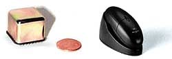
Photo 1. The new generation of gyroscopes, such as this one from Gyration, is based on vibrating structures rather than rotating masses. The devices can be fabricated in relatively small packages (left). A fully integrated device packaged for use as a wireless PC mouse is on the right. (Courtesy of Gyration.)
Vibrating Reed
This is subject to the null problem when certain directions of acceleration and rotation are applied to the descending body. Compensation should be possible by placing four of the devices on the corners of a tetrahedron as suggested for the accelerometers.
Ring Gyroscope
This is the only device that can follow changes in direction whatever the forces on the descending body. A triple-axis device must be used to ensure knowledge of three body axes as they change during the descent.
Summary of the Problem
A body in free fall has no inclination with respect to itself because it is impossible to establish a reference to the local gravitational field. There are two approaches to providing an estimate of a suitable measure of inclination for such a body. The first is to make measurements from a platform with a known orientation with respect to the local field (e.g., a videotape history of the descent). The second is to keep a complete history of the motion of the body about its center of mass. Instrumentation for the second approach is possible if the problems of drift and offset are solved and the problem of instrument nulls is avoided or compensated.
Instrument Requirements Good, Fast, or Cheap?
The techniques summarized above have served the Army well in their current modes of use. The problem is that the costs associated with the required instrumentation limit the number of instrumented drops to 5060 per year. Some of these are one-load and some are multiple-load airdrops (a load is defined as one independent platform suspended from its own parachute system). On the multiple load airdrops the number of loads can reach five from one aircraft. With the containerized delivery system, a single aircraft can drop as many as 40 bundles. In FY 1999, more than 2000 tests were conducted on airdrop testing of live jumpers and mannequins.
Figure 4. The fiber-optic gyroscope continues to be the standard by which other inertial sensing systems are judged. The high-quality fiber-optic coil required for the sensing element, however, limits the opportunity for cost and size improvements. (Courtesy of KVH Industries, Inc.)
An airdrop of either personnel or equipment is a complex mechanical system that responds in different ways to different stimuli. Oscillation, roll rates, and maximum angular deviation from a desired spatial plane contribute to the success or failure of any specific test iteration or system. Because the parachute and its payload constitute a mechanical system, it is logical that reducing specific stimuli that contribute to failure should result in increased overall system success. The velocity of the parachutist landing on the ground is a direct cause of injuries. Descent rate, wind drift, parachute maneuvers by the jumper, and oscillations all contribute to system velocity. Reducing the velocity should therefore reduce injuries and damage. Controlling and reducing oscillations will reduce total system velocity. An ability to accurately quantify oscillation and inclination is essential to efforts to reduce adverse oscillations.
Equipment airdrops can use the existing rate gyro system but the data are not easy to process and are sometimes questionable. An initial point for integration referencing is not always readily apparent. Rate gyro packages are too large to use with live jumpers and mannequins. With the concept of developing a new personnel parachute system (the T-10 has been in use since the 1950s), designs must recognize and compensate for increased weight loads on the parachute, faster aircraft, oscillation, and a variety of other factors.
As might be surmised, the odds are against catching faults when such a small percentage of the activity is monitored. If the instrumentation cluster could be made sufficiently low cost, all (or nearly all) of the drops could be instrumented to collect data that would facilitate research into preventing losses and validating new designs. The goal is to improve the odds.
All the requirements for the measurement system can be viewed as issues related to functionality (doing whats necessary), utility (doing it in a way that fits the existing infrastructure), or operability (can a person really use it?). If any one of these isnt given the consideration it deserves, the solution could end up like so many other good solutionsa curiosity on a shelf that just wont work in its intended application. By examining the requirements from this perspective we were able to come to agreement among the team members and the user community on the relative importance of each of a long list of needs and wants for the system.
Accuracy and robustness, perhaps not surprisingly, emerged as the top requirements for the delivered system. The unit had to survive the tremendous jerk of the chutes opening and the impact with the ground. The figures finally agreed on for the first prototype were:
Accuracy of ±0.5° inclination over the operating temperature range
Operating temperature range of 0°F120°F
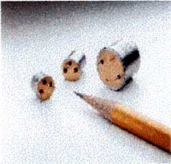
Photo 2. Accelerometers from Oceana Sensors are packaged in standard TO-3 cans to support standardized integration of systems. Three-axis accelerometers are required for full X,Y,Z sensing. (Courtesy of Oceana Sensors.)
Ability to survive an impact jerk of 50 g/s
The need for easy calibration, a simple zeroing technique, and a predictable and tolerable drift dominated the utility requirements. These turned out to be substantial technical challenges, aside from the utility requirement that user procedures be simple and effective. With the vision of ubiquitous sensing, labor-intensive procedures for these required functions could not be tolerated. The prototype could be tested with some deficiencies but a clear path to reduced impact on operations would be required.
Since any single test could involve hundreds of inclination sensors, calibration would best be implemented through automated and/or internal functions. The design calls for a device that, once calibrated, gives an indication that the calibration remains valid. Only devices whose calibration had drifted beyond accepted limits would require recalibration.
Any device measuring inclination must have a point of reference from which inclination is measured. Some sensor technologies provide this through a measure of the Earths magnetic field. Others simply use gravity. The key is to have a technique that supports reproducible results at any location on the globe.
The potential error introduced by the sensors DC drift is a direct function of the sensors physics. Since an accelerometer-based inclination sensor produces a signal proportional to acceleration, it must be integrated twice to get a measurement of inclination. Drift errors of only a few tenths of a percent make the indication totally unusable after a relatively short period of time. Given that such a design would most likely require six such accelerometers, the potential for errors becomes even worse. Drift can be caused by time, temperature, vibration, or various other environmental factors. The key is to make sure that the overall error budget is not exceeded.
The most successful systems in current use are based on mechanical gyroscopes. These dont have trouble meeting the accuracy requirements but they have little chance of meeting the cost, size, and weight restrictions that have prevented their wide-scale deployment. Their power drain necessitates turning the system off during the time between calibration and final deployment. The power-up sequence is then executed just before the actual drop. This is an operability problem since arming a sensor package is not a part of the normal pre-jump sequences carried out by paratroopers or other personnel.
The deployment costs for these systems are currently dominated by the purchasing price. This could change, however, as the new microelectromechanical systems (MEMS)-based devices become available. The operations costs (calibration, zeroing, and data retrieval) could quickly dominate once the purchase price is brought to the point required for wide-scale deployment. Our approach is to make sure that these costs are addressed in concert with the cost reductions available through the MEMS-based devices.
What We Found
Our study revealed that almost all devices designed to measure inclination rely on the same three underlying principles: The Sagnac effect (laser ring gyros), angular momentum (gyroscopes), and inertia (accelerometers). We will now describe each principle, the types of devices available, and the way these devices might meet the Armys requirements. Later on we will take a look at combination devices including gyroscopes and accelerometers that measure overall motion characteristics. Then we will describe some of the critical design issues that will determine the overall success of the final implementation (like setting the zero). Finally, we will suggest a path forward, based on the details presented here and on our understanding and assessment of where the technologies are headed.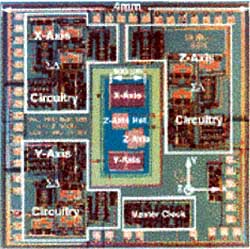
Photo 3. Fully integrated, MEMS-based inertial measurement systems are based on vibrating structures built on a micron-scale platform and can supply full X,Y,Z indications. Commercialization of this technology holds tremendous promise for inertial measurement. (Courtesy of the Intelligent Micromachine Initiative, Sandia National Laboratories.)
The Sagnac EffectLaser Ring Gyros
Laser ring gyro technology has led to fiber-optic gyros (FOGs), key components of reliable, robust, accurate systems that measure ~15 in.3 and can be bought for about $5000 (see Figure 4). They are usually of the interferometric type, in which fringes are optically detected to determine the differing path lengths the motion of the coil produces in the legs. The classic problem of locking-in when relatively small motions are involved has been solved by dithering the coil (or the signal) to ensure that a zero motion signal is not likely. Other refinements have reduced the drift to ~1 m°/hr. for the most expensive devices to ~10 m°/ hr. for the $5000 devices cited here.
These devices generally read out in rate of change of inclination, requiring only a single integration to get the actual angle of inclination at any given time. This could be a source of error since small errors over time will get integrated into large errors. The drift in these devices is usually caused by nonhomogeneities in the fiber, a problem that can be solved only by purchasing expensive high-quality optical fiber. Finally, the setting of the zero inclination angle becomes the limiting factor for the absolute accuracy of the measurement.
The operating principle is the Sagnac effect, which is also the basis of the ring laser gyro. When the coil is not rotating, the light paths in both directions are of equal length. If the coil is moving in a plane parallel to that of the coil (![]() ), the path for one of the directions is shorter than the other and an interference pattern is generated on the detector.
), the path for one of the directions is shorter than the other and an interference pattern is generated on the detector.
An exciting new technology, embedded electro-optics, could overcome the cost and size limitations of the current generation of FOGs. Research at Oak Ridge National Laboratory hints that it might be possible to fabricate nanometer-scale waveguides directly in thin films such that a 70 m optical path length can exist on a single 2 cm2 substrate. Embedded electronics would then provide the phase readout necessary to measure the movement of the inertial frame. No one has yet claimed that this will work, but some of the researchers think it is worth pursuing.
Angular Momentum (Gyroscopes)
The wheel-type gyroscopes have given way to a new type called Coriolis vibratometers (see Photo 1), which replace the rotating mass with a vibrating mass. Any motion that results in a change in the plane of the vibration of the mass produces a reactive torque that can be used to calculate rate of change of inclination. Here again the signal must be integrated to derive the angle of inclination from the rate. The inspiration for this type of gyroscope dates back to early studies of insects and how their flight trajectories are stabilized.
The Coriolis force based devices also present opportunities for cost and size reductions thanks to MEMS fabrication techniques. New integrated packages capable of meeting most of our requirements are rapidly approaching the commercial market. Gyration, for example, offers $15 devices for applications such as a mouse substitute for PCs.
These inexpensive devices do not exhibit the long-term stability and wide temperature range of the more costly alternatives. The Gyration Microgyro 100 generates a signal indicating rate of change in the angle of inclination in degrees per second. The signal can show a long-term drift as much as 0.2º/s and a temperature drift of 0.2°/s/ºC. The benefits of low cost and inherent ruggedness are offset by concerns about drift. Compromises, such as including a temperature sensor, might gain this sensor a place in our application.
Two factors bound the operating conditions the Gyration device can tolerate. The magnets that drive the oscillation begin to change their properties below about 5ºC. A critical failure occurs if the device is subjected to a vibration that is a harmonic of the vibrating members natural frequency of oscillation, but since this frequency is in the kilohertz region, it would not be a problem in our application.
Inertia (Accelerometers)
Accelerometers (see Photo 2) are designed to detect changes in rectilinear motion (X,Y,Z). Using these devices to detect inclination requires mounting three of them on a platform that is rotated with the package to yield traditional roll, pitch, and yaw. Accelerometers probably hold the most potential for cost and size reduction because of the automotive industrys interest in using them for motion measurements that will update suspension, passive restraint, and braking systems information.
The MEMS-based sensors promise tremendous reductions in size and cost. The latest laboratory demonstrations include fully integrated inertial systems on a single chip (see Photo 3).
Currently available packaged systems offer some interesting opportunities but all accelerometer-based systems have the same basic potential problem. Since the underlying measurement is by definition acceleration, two integrations are required to derive the displacement vector necessary to compute inclination. Any small errors that appear in the acceleration meas urement will continue to add over time and produce significant errors in the computed displacement vector. Accelero-meters used for meas uring inclination must include a mechanism for mitigating the effect of this double integration on the potential error. One way to solve the problem is to include multiple sensor types in the same package.
Combination Devices
The latest devices combine into a single package the best features of accelerometers and gyroscopes. Advances in MEMS technology suggest that these combinations can be fabricated on the same piece of silicon, producing a very robust and potentially low-cost sensor. The future looks promising, but the devices are still costly and/or impractical for real-world applications.
Conclusion and the Path Ahead
The marketplace is quickly moving toward low-cost, easy to use, sensor-based units for automotive and other consumer applications. Adapting them for use in military testing, though, might require some significant development. The solution we propose is to develop a system architecture that supports the plug compatibility of these new devices. A combination of devices, each supplying its part of the overall solution for integration into a system, would likely satisfy our functionality, utility, and operability requirements. We will be building a test bed at ORNL that will allow us to report on accuracy, robustness, and repeatability over the life of the device. We hope to deliver to the Army a prototype that can be used to predict purchasing, operating, and life-cycle costs, and, most important, to provide data that will help in the design and testing of parachutes for personnel and matériel that will get them to the ground safely.