

Background
Measuring the movement of the human body is a complicated task. People are mobile and move with many degrees of freedom. Furthermore, the body is an elastic structure that changes shape when meeting other objects. An ideal wearable sensor for measuring body motion needs to be able to deform during body movement and provide precise motion data while also being socially unobtrusive.
Body movement can now be monitored using soft and flexible sensors that transmit their signal via Bluetooth to a phone or computer. These stretch sensors are soft and flexible capacitors. When the sensor is stretched or squeezed, capacitance changes can be monitored electronically to provide precise information about the movement of a limb or pressure on hand and foot.
Stretch sensors also need circuits containing sophisticated algorithms that interpret the stretch data and convert it into useful information for the user. A stretch sensor and circuit are a starting point to discover a variety of exciting new applications in areas such as wearables, gaming and VR/AR.
When designing sensing applications it is critical to understand how sensor design relates to performance. Here we will take an in-depth look at sensor sensitivity, how it relates to geometry, and the impact of sensitivity on sensor accuracy.
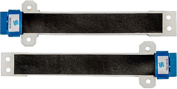
Fig. 1: A pair of silicone stretch sensors.
Next page
Basic operating principle
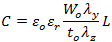
A stretch sensor is a flexible capacitor that can give precise information about deformation of shape. We do this by relating changes in capacitance to geometry according to the Parallel Plate equation:

where C is the sensor's capacitance, A is the surface area, D is the thickness, ε0 is the absolute permittivity, and εr is the relative permittivity of the dielectric layer.
Thus, the capacitance of a stretch sensor is directly proportional to the area of the parallel flexible electrodes and is inversely proportional to the distance between the flexible electrode layers. Stretching a sensor causes both the area and thickness to change. This deformation results in a measureable change in capacitance.
The area A is the width W multiplied by the length L. We can rewrite the Parallel Plate equation in terms of original dimensions as shown in figure 2 (e.g. W0, L0, and D0) and stretch ratios (deformed length/original length) where λy is the stretch in the width direction, λx is the stretch in the length direction, and λz is the stretch in the thickness direction:
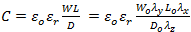
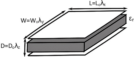
Fig. 2: Basic structure of a stretch sensor with dimensions labelled.
Next page
Calculating Sensitivity
For the following analysis, we consider the special case of uniaxial stretch in a sensor. Please note that the analysis changes if the sensor is in a more complex state of stress; involving say, stretch in more than one direction when the sensor is mounted in a smart textile or against a body. In the case of uniaxial stress, the extension – capacitance relationship is nearly linear as shown in figure 3 below and the area of the sensor remains constant during stretch.
Fig. 3: Graph showing capacitance vs extension for a uniaxially stretched silicone stretch sensor.
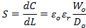
Sensitivity is simply the slope of the capacitance-extension curve. We can write this mathematically with the formulation below where S is the sensitivity, C is the capacitance, and L is the length of the sensor:

We start calculating sensitivity by rearranging the capacitance equation in terms of length:
In the special case of uniaxial tension in a volumetrically incompressible solid λy = λz we can rewrite the equation as:

Differentiating with respect to length L we get
It can be seen that the sensitivity (in pF/mm) of the sensor is not related to the length of the sensor. Sensitivity can however be increased by:
- Increasing the width (W0) of the sensor.
- Introducing more layers into the sensor structure, thereby increasing the effective width of the sensor.
- Creating thinner dielectric layers, thereby decreasing the distance between the flexible electrode layers (D).
- Utilizing dielectric layers with higher relative permittivity (ε0).
Next page
Using Sensitivity
The schematic in figure 4 below highlights the relationship between extension and capacitance for a high and low sensitivity stretch sensor. The high sensitivity sensor has a steep line on the graph, and the low sensitivity sensors are represented by a shallow line. This higher sensitivity can be very useful when trying to increase the accuracy of a sensor.
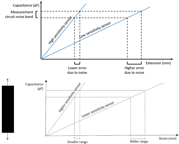
Fig. 4: Graphs showing the effects of sensitivity on sensor measurement accuracy in the presence of noise.
Measurement using a sensor can be shown schematically in a 3-step process. First, the capacitance is measured with an interrogation circuit. Second, a line is traced horizontally until it intercepts the sensor curve. Third, a line is then traced vertically until interception with the horizontal axis. This process can be seen in the below schematic which also includes the effects of noise. The dotted lines intercepting the capacitance axis represent the noise band in pF of the sensing electronics. A sensor with higher sensitivity has a smaller error band due to noise in the circuit.
Design Considerations
It is desirable to maximize the sensitivity of a sensor to gain the most accuracy. However, this comes with costs:
- Increasing width increases stiffness and is limited by the available space in the design.
- Adding layers increases size, stiffness, manufacturing complexity and cost.
- Thickness can be changed but normally is already minimized up to the limit of manufacturing constraints.
- Changing the dielectric constant will change the mechanical and manufacturing properties of the sensor.
Even if these options are exhausted improvements in accuracy can still be obtained. In the above schematic it can be seen that reducing interrogation noise would increase accuracy. This reduction can be achieved using methods such as filtering, shielding, or using higher specification electrical components. Each method has its own pros and cons.
Conclusion
Stretch sensors are a great prototyping tool for technologists. The benefits of being wireless, soft, and lightweight make them ideal for embedding into clothing or attaching directly to the body. These characteristics make it possible to explore new applications that rely on precise body motion information.
About the Author
Dr. Benjamin O'Brien is the CEO of StretchSense and a pioneer in the wearable sensor industry. After co-founding StretchSense in 2012, Ben won the Prime Ministers MacDiarmid Emerging Scientist Prize, and in 2015, he won the New Zealand Hi-Tech Young Achiever's Award. He is passionate about applying innovative research to commercial applications. He envisions a future of wearables that are so unobtrusive they are invisible to the user.
About StretchSense
StretchSense was founded in 2012 with the aim of developing precise body motion sensors for wearables. Today, StretchSense is working with leading companies to develop smart clothing and new VR/AR inputs for gaming, fashion and entertainment. In the long term, StretchSense is working on energy harvesting technology to create self-powered sensors for truly unobtrusive wearables. For more info, visit http://www.stretchsense.com.
Related Stories
Active Signal Characterization Boosts Accuracy Of Wearables
North America Wearable Sensors Market Expected to Reach $118.62 Million by 2018
Fitness Wearable Tech Startup Actofit Launches its Much-awaited Gym Fitness Tracker