
In most processes the critical variable is mass, not volume. Volumetric flow meas urements are less reliable than mass flow measurements because changes in gas temperature and pressure change the density of a fixed volume of gas. In the control system, additional errors can be propagated by backpressure fluctuations in the process being monitored.
In contrast to rotameters, turbine meters, and other volumetric flow devices, thermal mass flow meters (MFMs) and mass flow controllers (MFCs) are relatively immune to changes in inlet temperature and pressure. The MFM/MFC is the only device capable of providing direct measurement of mass flow (see Table 1). Most other methods measure volumetric flow (Q) and require separate measurements of pressure (P) and temperature (T) to calculate density and mass flow (m). Because the MFC meas ures and regulates molecular flow, it provides the most reliable, repeatable, and accurate method for delivering material at a desired rate from a supply volume to a process.
mTable 1
Flow Meter Type
What Does It Measure Directly?
Comments
Turbine meter
Need P, T
Positive displacement
Need P, T
Orifice plate
Need P, T
![]()
Rotameter
Need Pm, Tn
Thermal
Measures mass directly
Accurate, repeatable gas flow control improves combustion and chemical reactions, facilitates analysis, and reduces material waste. Originally developed for chemical vapor deposition in the semiconductor industry, capillary-type thermal MFCs are now widely used in laboratory, continuous process, discrete manufacturing, and QA applications.
The Thermal Sensing Principle
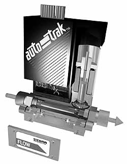
Photo 1. The mass flow controller integrates a thermal mass flow sensor with a servo control valve and PID electronics.
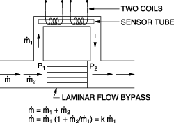
Gas enters the flow body and divides into two flow paths (see Photo 1). Most of the flow goes through the laminar-flow bypass, creating a pressure drop that forces a known fraction of the flow through the sensor tube.
Two resistance temperature detector coils around the sensor tube direct a constant amount of heat into the gas stream. Heat transfer between these elements results from interaction with the molecules of the flowing gas, independent of pressure or temperature fluctuations.
In actual operation, the gas mass flow carries heat from the upstream coil to the downstream coil. The downstream coil therefore has a higher temperature and more resistance than the upstream coil. The coils are legs of a bridge circuit with an output voltage proportional to the difference between the coils resistance, which in turn is proportional to the mass flow rate in the capillary tube. The two other parameters, heat input and coefficient of specific heat, are constant (see Figure 1).
The Control Valve
In the MFC, the gas leaves the sensor and the bypass and flows through the servo control valve. Most MFCs incorporate an electromagnetic valve, similar to an on/off solenoid valve, except that the current to the valve coil is modulated so that the valve plug assumes the exact height above the valve orifice necessary to maintain the commanded flow. Built-in PID electronics allows the device to maintain continuous proportional control by comparing the meas ured sensor signal to the commanded flow rate. MFC control valves are available in a variety of materials, in either normally open or normally closed configurations, and with a wide range of input, output, and command signals.
Instrument Accuracy
A
B
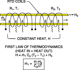
Figure 1. The laminar flow element forces a known fraction of the flow through the sensor tube (A). Mass flow through the tube is inversely proportional to the temperature difference between the coils (B).
The accuracy of MFMs and MFCs is determined by two factors: flow calibration and repeatability. Proper instrument calibration ensures starting point accuracy, and repeatability is the measure of continuous performance-to-specification over the lifetime of the device. Most thermal MFMs and MFCs are specified at ±1% of full-scale accuracy and ±0.25% of full-scale repeatability.
Thermal MFMs and MFCs are gas-specific devices and must be calibrated with either the actual gas or a reference gas. This inconvenience has led to the development of many fixes in the industry, and is driving the development of smarter devices. For the time being, however, primary calibration with the actual gas or a gas of similar molecular characteristics is the only way to achieve accurate starting point accuracy.
Several factors can affect repeatability. High-stability materials and electronic components, and precise internal voltage and current regulation prevent long-term drift. Sensor and bypass design also plays a major role in preventing errors caused by contamination and clogging. U-type sensor tubes exhibit residual stresses from bending, which can cause long-term strains and unraveling of the sensor coils. These sensors are also more likely to develop drift due to contaminant deposits.
Consideration should also be given to the bypass element of an MFM or MFC. Accuracy can be degraded by changes in temperature if the bypass is an orifice, as opposed to a pure laminar flow element (see Photo 2). The orifice or venturi does not provide laminar flow, and the pressure drop is proportional to the square of the bypass flow. In this case, the ratio of bypass flow to sensed flow is not a constant, but instead is a complex nonlinear function with temperature-dependent terms, e.g., gas viscosity. Both the nonlinearity and temperature dependence of the orifice bypass can seriously degrade the accuracy of MFCs.
Applications for MFMs and MFCs
MFMs and MFCs effectively reduce costs and improve productivity and measurement accuracy in a variety of analytical, process, and OEM instrument applications. Automating gas delivery with an MFC has many advantages. Because the instrument measures and controls mass flow directly, it is unaffected by temperature or pressure changes in the gas stream and can be operated under positive or negative (vacuum) pressures. In laboratory or test applications, it is easier and more efficient to supply a set point to the flow controller than it is to manually adjust a needle valve with a rotameter indication. The MFM or MFC also allows the user to capture important instrument and process information for data analysis, SPC, or quality audits.
Photo 2. A machined stainless steel bypass creates pure laminar flow through the sensor.
Developed originally to control gas vapor deposition in semiconductor fabrication, MFMs and MFCs can now be found in almost every industry. Any operation that requires precise measurement or control of low-flow clean gases can benefit from this measurement technique.
Gas Moisture Analyzers. Dry gas is especially crucial to productivity in the semiconductor industry, where there is a clear relationship between gas purity and wafer yield. Moisture levels must be constantly monitored in the parts-per-billion range.
Moisture analyzers, the most commonly used devices to measure moisture concentration, require precisely controlled flows of gas (see Figure 2). Rotameters and needle valves have been used for this purpose but are prone to error because they cannot compensate for pressure and temperature variations in the gas stream.
The need for manual adjustments and extensive calculations also contributed to system inaccuracy. The MFCs 1% full-scale accuracy, fast response, and electronic set point control maximizes analyzer reliability and efficiency.
Other analytical applications include sample preparation for gas chromatography and mass spectrometry, flow control to gas generators and gas analyzers, pilot plant development, and gas blending.
Vapor Deposition and Sputtering. In the sputtering process, a negatively charged electrode is slowly disintegrated by molecular bombardment (see Figure 3). The sputtering medium is usually argon because this gas generates sufficient momentum to free atoms from the target. In a vacuum environment, these free target atoms deposit themselves on the surface of the material and form the desired coating or plating.
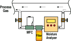
Figure 2. Automating gas flow control to the moisture analyzer ensures precise, reliable measurement.
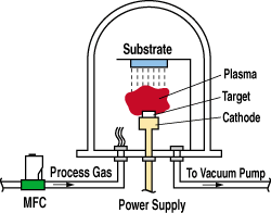
Figure 3. In a vacuum process, the mass flow controller automatically compensates for fluctuations in system pressure.
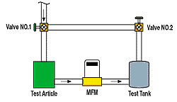
Figure 4. The mass flow meters exceptional low-flow sensitivity makes it well suited to leak testing and orifice sizing.
Maintaining a specified gas flow rate to the vacuum chamber is essential to the proc ess. Typically, vacuum pumping stations require a throttle valve or an orifice-limiting device to control the pumps output when the sputtering gas is introduced. This method is extremely pressure sensitive and can result in inefficient gas delivery and poor product quality. The MFC automatically compensates for changes in system pressure caused by vacuum pump fluctuations, and delivers a precisely controlled gas mass flow rate to the chamber.
Other industrial applications include chemical tank blanketing, sparging airflow to fermenters and bioreactors, combustion control, gas fill, flame control, aluminum purification, laser and plasma welding, and gas blending.
Leak Testing. Stringent production test requirements demand fast, accurate, consistent readings that can be electronically stored for analysis. The most precise technique for leak testing is to use a thermal MFM to measure flow rate through a test article (see Figure 4).
The MFM provides a fast, reliable meas urement and produces test data ideally suited to leak detection and diagnostics. Its exceptional low-flow sensitivity allows detection of leaks in both small- and large-volume enclosures. Other test and QC applications include orifice sizing and flowmeter calibration and validation.
Sizing and Specifying the MFM/MFC
Understanding the principle of operation and calibration requirements of the MFM/MFC helps users specify the best instrument for a particular application. As is the case with most instrumentation, the application conditions must be completely and accurately known to avoid costly mistakes that can delay a startup or even damage the finished product. The most important information requirements for specifying an MFM or MFC are gas type, estimated flow rate, pressure and temperature range, and, for an MFC, the differential pressure.
Once the flow parameters have been defined, the proper flow body size can be determined by following these steps:
1. Consult the manufacturers product specifications for the acceptable flow range of each flow body.
2. Convert the estimated flow rate to the corresponding units listed in the product specifications.
3. If the gas to be measured is not nitrogen, convert the flow rate to the equiva lent nitrogen flow rate. This is done with a linear correlation or a K factor, defined as the ratio of the actual gas flow rate to the equivalent nitrogen flow rate. To obtain the equivalent nitrogen flow rate, divide the actual gas flow rate by the K factor.
4. Select the flow body size that will accommodate the estimated flow rate.
5. Ensure that the differential pressure falls within the acceptable range for the selected flow body size and flow rate.
Flow rate: Inlet pressure: 03.6 scfh 30 psigTable 2
Gas:
Argon
Outlet pressure:
0 psig (atmosphere)
Temperature:
80°F
Sizing Example. Consider the application specs in Table 2. Then apply the five steps as follows:
1. Manufacturer: Sierra Instruments Model 840
a. Low-flow body: 015 slpm nitrogen
b. Medium-flow body: 0100 slpm nitrogen
c. High-flow body: 0500 slpm nitrogen
2. Convert the units:
3.6 scfh (1 H / 60 min.) (28.316 l / ft3) = 101.94 slpm
3. Convert flow rate to equivalent nitrogen flow rate. The K factor for argon = 1.45. QEQUIVALENT NITROGEN = (QACTUAL GAS / K) = 101.94 slpm / 1.45 = 70.3 slpm
4. The applications equivalent nitrogen flow rate of 070.3 slpm falls within the capabilities of a medium-flow body.
5. The differential pressure is 30 psid, at 70.3 slpm of nitrogen. This falls within the acceptable range of 5150 psid.
Emerging Technology Developments
The innovations and practical improvements emerging or developing in the world of thermal MFMs and MFCs include:
Improved gas correlations
Microprocessor-based transmitter design
Product packaging improvements
Stand-alone configurations
Improved Gas Correlations. The established method of calibrating the MFM/ MFC has been to develop K factors that make it easier and more practical to size and calibrate a device. This has been especially important when applying the instrument to toxic or lethal gases because the K factor allows the manufacturer to calibrate the MFC with nitrogen, a safe and inert gas. The disadvantage of this technique is that it does not perfectly model the correlation between nitrogen flow and the actual gas, especially for less-common gases, higher flow rates, and higher pressures. A major breakthrough has been the development of new gas correlation equations that allow the manufacturer to more accurately model the actual gas, resulting in significant improvements in installed performance.
Microprocessor-Based Transmitter Design. The development of improved gas correlations, combined with new micro proc essor-based designs, has greatly en hanced MFC performance and ease of use. Microprocessors allow the manufacturer to calibrate the device with nitrogen and apply it to any gas by merely downloading the appropriate gas equation into the device memory. Better gas equations also improve linearity because of higher resolution of the calibration curve.
Operators also benefit from the flexibility of the new digital MFM/MFC. The ability to load any gas equation into the digital MFC is ideal for multiple gas applications and reduces stocking requirements. Other benefits include self-calibration and diagnostics, digital communication and control, and easier commissioning and field configuration.
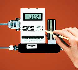
Photo 3. The latest generation of mass flow controllers features onboard display and set point control to facilitate setup and flow rate adjustments.
Product Packaging Improvements. The application base for the thermal MFM/ MFC has grown tre men dously in the past 30 years. Initially developed for use in a clean semiconductor wafer fabrication facility, the instrument enclosure did not need to withstand harsh elements or hazardous area conditions. Today, many of these devices are being applied in the pharmaceutical and chemical manufacturing industries and require a much more rugged construction. For example, the ultraclean demands of a pharmaceutical plant expose the MFM/MFC to external cleaning in the form of a chemical washdown that would damage the conventional MFC package. High demand for thermal MFCs in these harsher environments has driven the development of NEMA 4X and explosionproof package designs.
Stand-Alone Configurations. The conventional MFC is installed in conjunction with an electronic display and power supply module whose purpose is to provide power, a command signal, and a display of the measured variables. The newest MFCs are available with a local set point and display configuration that is well suited to applications where real estate is scarce, such as in many OEM applications where there is a need to incorporate many components within a secondary product enclosure, or in laboratory applications where benchtop space is limited (see Photo 3).
The conventional MFC also requires a dual-polarity power supply. The stand-alone MFCs are equipped with a single-sided power supply that eliminates the need for expensive and space-consuming power conversion units.
Second, the MFCs provided more information. By monitoring and metering gas ratios precisely, they proved an elegant and relatively straightforward way of measuring oxygen uptake rate. The digital MFC also facilitates the cGMP- and FDA-required validation of fermentation processes, which calls for documented evidence of consistency in specifications and quality. This includes detailed records on specifications, performance, maintenance, and calibration history of all instrumentation devices associated with the bioreactor.MFCs Improve Performance of Pilot-Scale Cell Culture System
First, the group needed to minimize the formation of foam in the bioreactors headspace. To accomplish this, PDL had to reduce the net volume of air and oxygen gases that were being bubbled into the culture medium. The rotameter PDL had been using was unable to control the low flow rates required. According to the rotameters flow tube, the flow rate was 60 ml/min., but after Sierras MFCs were installed the true rate was discovered to be as much as 3 3 higher. Setting the MFCs at 60 ml/min. significantly reduced the foam.
Summary
The thermal MFM/MFC attributes of excellent low-flow sensitivity, immunity to pressure and temperature changes, and built-in control elements have led to their use in thousands of gas flow applications.
Emerging technological developments and packaging options have made these devices less costly, more reliable, and easier to apply. The benefits of mass flow measurement and automated gas delivery easily outweigh the inconvenience factors associated with the device, and have driven the growing and widespread acceptance of this technology.