
Motion control and machine vision are used throughout the semiconductor manufacturing process, from monitoring the diameter of ingots as they are formed from a crystal seed to aligning a die lead frame prior to wire bonding. In nearly every step of the process, motion and vision can be found working together to align, inspect, measure, and identify wafers and die so that the various pieces of equipment can do their tasks.
Point Technologies, Inc.—a supplier of precision electrochemical pointing and micromachining services and products for small-diameter wire and tubing to the semiconductor, medical, and biotech industries—has recently applied motion and vision to the new area of probe needle inspection for the semiconductor industry.
Eyeing the Needle
Semiconductor manufacturers rely on probe needles to test ICs during the final phase of production to ensure that only the functional ones get packaged for final use. A probe needle is a straight, small-diameter metal wire with one end tapering down into a sharp point (see Figure 1). Probe needles establish an electrical connection between tester and IC by contacting the metal bond pads on the wafer.
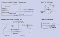 Figure 1. If probe geometry is inconsistent, the reference diameter, bend angle, tip diameter, and tip length will be inconsistent. |
Generally hundreds or thousands of probe needles are assembled into an array on a device called a probe card, which is tailored to interface between the specific type of IC being tested and the wafer prober. During testing, precise needle geometry is essential to ensure test data reliability and consistency for several reasons. First, when the prober aligns with the wafer being tested and then lowers the probe card onto the IC, the needles flex on contact with the wafer, causing the tips to slide across the metal pads. Probe tip diameter is a critical dimension that determines the area of the pad that is scrubbed.
Next, the needle's diameter and taper shape determine how much it will flex, and how much force it will apply as it touches down on the wafer. This is called the Balance Contact Force, a critical contact pressure specification set by the manufacturers that affects probe card life and the probe tip's ability to break through a thin layer of aluminum oxide on the metal bond pads to the metal beneath.
Finally, the probe tips must be precisely bent before assembly onto the probe card; this requires precise and careful work. Most probe card manufacturers use a reference diameter to determine where to bend the probe. If probe geometry is inconsistent, the reference diameter, bend angle, tip diameter, and tip length will be inconsistent. Any of these problems can cause probe misalignment and result in inconsistent test data.
Because probe needle geometry is vital for a successful test operation, Point Technologies, in the past, relied on a combination of manual video inspection systems and optical comparators to provide probe card manufacturers with needles that met stringent requirements. However, with rising IC production volumes and increasing demand for probe needles, this process was far too labor-intensive. Because needle inspection accounted for a significant proportion of the total manufacturing time, it was a prime candidate for automation.
Setting Its Sights on Automation
In late 2003, Point Technologies started investigating ways to improve its needle inspection process. Commercially available equipment was too cumbersome, slow, and expensive for its needs, so an engineering team from the company set about designing their own system.
The major design goals were to increase measurement throughput, accuracy, and repeatability while reducing inspection time. The system should also automatically document all measurements onto a shared server, minimize operator training, and maximize operator comfort. Finally, it should automatically plot the measurement data on a graph for comparison to customer specifications and to provide statistical analysis for process improvements.
The engineering team set out to master the art of integrating motion control and machine vision. They evaluated the feasibility of using a machine vision system to improve the measurement efficiency and still get repeatable measurements within 0.00002 in. With little machine vision experience, they chose to start with an In-Sight vision sensor from Cognex. The sensor's ease of use allowed the engineers to quickly familiarize themselves with its operation; without attending any formal training classes it took ~30 hr. to get comfortable enough with the In-Sight to set up the inspection routine.
While the sensor was a good validation tool, it wasn't the right product for the final application. Although the In-Sight measured the needles and output the data, the design team chose instead to use a Cognex VisionPro PC-based vision system because of its higher performance and more seamless integration with the motion control system. The PC-based vision system uses a Cognex MVS-8100D Series frame grabber inside of a basic Dell PC, and a high-resolution (1280 x 1024) Cognex CDC-200 digital camera.
One of the most challenging parts of any machine vision application is setting up the system so it can produce a good image. After experimenting with lighting and optics, the team implemented a high-magnification telecentric lens that eliminates optical distortions and a 2 x 2 in. diffuse LED backlight to provide suitable images with the necessary resolution.
Vision Meets Motion
The motion control system of the newly developed PointScan probe needle inspection station uses limit switches but all other input comes from the vision system. Engineers blended the vision, motion control, operator interface, network communications, and database using MicroSoft Visual Basic 6.0 on the PC. All logic and control is managed with Visual Basic, allowing stepper motors to move the camera and position the needles. Vision-guided motion applications such as this require a very fast vision system that will synchronize image capture, analysis, and measurement with the motion required to find the needle, focus on the needle, and move from needle to needle (see Figure 2).
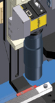 Figure 2. The image formation subsystem consists of a CMOS-based digital camera, a high-magnification telecentric lens, and an LED backlight. The vision system communicates with the motion system as it moves the camera up and down to focus on the needle. |
Point Scan's motion control system is essentially a tabletop Cartesian robot that uses precision stepper motors to drive three axes of motion (see Figure 3). One axis moves the loading table into and out of the inspection area and the other two axes control camera movement. One axis moves the camera horizontally; the other moves it vertically. The motion system combines assorted components such as a three-axis motion controller, precision linear slides, leadscrews, and stepper motors.
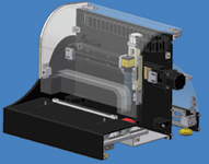 Figure 3. PointScans motion control system includes three axes of motion. One moves the loading table into and out of the inspection area; the other two axes control camera movement. |
The design team's previous experience building multi-axis automation systems made the mechanical design pretty straightforward, though there were some challenges. For example, due to the very small size of the probe needles and the high magnification of the vision system, special care was taken to isolate the system from vibration by eliminating sources of vibration within the machine design and by using vibration dampers.
Another challenge arose when considering camera resolution, optics, and working distance to achieve the desired field of view (FOV). The entire length of the part being measured didn't fit into the FOV, so the part had to be moved a fixed distance under the camera to complete the taper length meas-urement. This complicated the application because it required combining the information from more than one image.
Finally, integrating vision and motion required the engineers to calibrate the vision system with the motion system. The vision system tool suite includes special algorithms to correct for errors such as optical distortion from the lens or perspective changes due to camera mounting angle.
Lights, Camera, Inspection
Prior to inspection, 200 blank, straightened wires are loaded into a transferable fixture or "block" and then tapered in a proprietary electrochemical pointing (ECPTM) process. The needles are inspected in their holding fixtures in process and after completion.
For inspection, the operator carries the block of probes to the PointScan, and selects their name on its flat panel touchscreen. The specifications for every job are stored in a shared database, so after setting the fixture down on the loading table, the operator presses 'Go' to start the inspection. The loading table automatically moves the probe needles into the inspection area. From the side, the camera moves over the top of the needles until its FOV intersects the first needle, then the table backs up until the camera locates the point.
To optimize measurement accuracy, repeatability, and reproducibility, PointScan also includes an automatic focus routine. During this step, the vision system communicates with the motion system as it moves the camera up and down to focus on the needle. Once the needle is in focus, the vision system acquires the image, analyzes it, and makes the appropriate measurements. The data are automatically recorded and the camera jogs to the next needle to be measured.
As measurements are recorded, PointScan automatically plots the data on the screen so that the operator can see if they are within the specification. At the end of the inspection, or if the operator presses 'Stop,' PointScan automatically unloads the needles and the operator accepts or rejects them (see Figure 4).
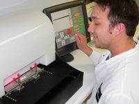 Figure 4. The PointScan automated needle inspection system integrates machine vision and motion control to inspect needles faster and provide more accurate measurments than inspection techniques used formerly. |
If the parts are rejected, the operator will need to rework or make new parts and can use the inspection data to adjust his or her process. If the parts are accepted, a label is printed to allow future reference to the inspection data. At the end of the job, the system generates an inspection report to accompany each shipment that includes all of the data for the measured parts and compares it with customer specifications. The report helps streamline quality issues by clearly communicating specifications and measurements to the customer. Providing actual meas-urement data distributions also helps customers to better model their processes.
Intelligent Inspection
Machine vision has enabled the design team to create an inspection system where a computer does all of the inspection and most of the data analysis. It used to take a person about 20 min. to measure 12 needles and record the data on paper. PointScan measures 12 needles in <2 min., records the data, and automatically graphs the data for the operator (see Figure 5). Since late 2004, five systems have been built and are being used in production. While the systems are primarily used for measuring probe needles they are also used for measuring electrosurgery needles for the medical device industry.
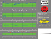 Figure 5. PointScan does all of the inspection and most of the data analysis, automatically graphing measurement data for operator comparison to customer specifications. |
Machine vision has proven invaluable for accurately gauging very small parts and providing quantitative results that can be used to track parts and productivity. It also provides great insight into the production process. PointScan provides the feedback needed for operators and the quality team to successfully remodel systems and processes to achieve built-in improvements and greater efficiency.
As a result of their experiences and success, Point Technologies sees machine vision and motion control as key for the future of manufacturing. Integrating vision with motion is not as difficult as some would have you believe. It takes time, money, and expertise, but done right, even the most challenging applications can pay off.
Dr. Dave Senders, B.S., M.E. and Steve Neely, B.S., M.E., can be reached at Point Technologies, Inc., Boulder, CO; 800-557-7059, [email protected], [email protected], www.pointtech.com. John Lewis, B.S., Ch.E. can be reached at Cognex Corp., Natick, MA, 508-650-3000, [email protected], www.cognex.com.