

If your cutting tool could talk, what would it tell you? At the International Machine Tool Trade Show 2008, we posed this question to machinists and manufacturing engineers from a variety of metal-cutting industries, job shops, and research labs. Despite the diversity of their backgrounds, all the professionals expressed a desire for feedback about part condition, machine dynamics, and cutting-tool health. With this data, they felt they could increase the material removal rate (MRR) of difficult substances, such as inconel and titanium alloys. Many participants described traditional machining, based on conservative best practices and rules of thumb, as "driving blind." Most of the engineers believed that information from sensor-enabled smart tools would result in more optimal conditions, reduced costs, increased MRRs, and improved part quality.
Barriers
Annual U.S. expenditures on machining operations are estimated to be in excess of $200 billion, about 2% of the gross domestic product. In December 2002, the National Institute of Standards and Technology hosted the "Smart Machine Tools" workshop. The event was organized by the Integrated Manufacturing Technology Initiative to "assess the needs, opportunities, and requirements for increasing the intelligence of machine tools for material removal." Two of the top priorities of the participants were the establishment of physics-based process models for a smart machine-tool test bed and the collection and analysis of the information necessary to determine machine conditions.
Although sensing technologies and process control are key elements of computer numerical control (CNC) automation, the machining industry has not widely embraced the use of high-bandwidth sensors for process feedback. The community's attitude toward sensor systems has been significantly influenced by the limiting configurations, lack of practical implementations, and high cost associated with high-bandwidth machine-tool sensor products.
Further, machine-tool sensor developers have focused on laboratory-grade products that do not satisfy the needs of production metal cutting. Although numerous commercial sensor options are available for machine tools, there are many hurdles (see sidebar "A Barrier to Sensor-Machine Tool Integration") including low durability, complicated set-up, intrusion on the machining envelope, and adverse effects on machine stiffness. Moreover, traditional machining sensor systems require wired or close proximity data acquisition (DA) hardware and do not provide data from within the tool.
As a result, the industrial segment of the community has minimal interest in high-bandwidth (kHz+) sensor systems for torque, force, and vibration monitoring. Research from Rehorn et al. explains this attitude: "This lack of interest in vibration is most likely due to the fact that it is difficult to put accelerometers near the cutting site, let alone in the tool."
Recently, however, the goal of collecting data from within a cutting tool has been realized through the development of a wireless sensor that can be integrated into a tooling system. This has become practical only with the availability of mature communications protocols such as Bluetooth and ZigBee and the proliferation of high-tolerance insert-type cutting tools. The combined functionality of the two technological advances makes high-bandwidth sensor implementations more attractive to the machine-tool community.
The Challenge
The difficulties encountered in deploying high-bandwidth sensors in cutting tools are particularly apparent in drilling and end-milling applications. In these operations, the tool rotates at high speeds and cannot be physically attached to a DA system. Historically, the ability to record in-process data from a rotating tool has been limited by sensor-deployment restrictions. Often, sensors such as accelerometers are mounted on the workpiece or machine spindle, far from the cutting process. Remote sensing locations reduce signal strength, introduce unwanted dynamic effects, and can interfere with machining operations. In addition, noncontact sensors, such as laser interferometers, can be disrupted by metal chips and cutting fluid present in the cutting process.
Recent research has examined prospects for placing wireless temperature sensors in rotating tooling. To observe metal-cutting machine dynamics, however, you must collect data at higher frequencies. Vibration, torque, and force data contain a broad spectrum of useful information but require significantly higher bandwidth than temperature measurement. Although spindle-mount dynamometers are available for force and torque measurement, they are notorious for making the machine spindle more flexible, and commercial units are delicate laboratory instruments that sport not-so-delicate price tags.
An Application-Based Solution
Suprock Technologies has developed tool-tip vibration, torque, and temperature sensors that are directly integrated with insert-type metal-cutting tools. The company's approach does not affect the stiffness of the tool. Suprock chose the Class 1 Bluetooth 2.0 EDR transmission method because it provides sufficient bandwidth and range over an ISM radio band. Figure 1 shows several variations of its sensor-enabled mill tooling system.
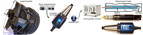 Figure 1. Prototype sensor-enabled tooling systems for end milling (Click image for larger version) Figure 1. Prototype sensor-enabled tooling systems for end milling (Click image for larger version) |
Interference, Channel Fading, and Coherence. During the machining process, the spindle and bed motors generate a wide and continually changing spectrum of interference. This can compromise wireless transmissions generated by fixed-frequency or fixed-amplitude radios. You can overcome the problem by characterizing the motor noise spectrum and designing a transmitter that avoids the interference in the milling process, or you can use an active noise-avoidance scheme.
To accommodate the multitude of milling configurations and processes, the system is based on frequency-hopping spread-spectrum (FHSS) transmission. This approach ensures more robust communications, despite ambient interference prevalent in machining environments. In addition to avoiding interference, FHSS is a good choice for factory settings where multipath effects can cause drops in signal strength. By changing the transmission frequency, channel fading is minimized. As a result, the coherence of the signal is unaffected by the machine-spindle rotation. The device has been tested up to 10,000 RPM with no effects from the changing transmission path.
Practical Design Constraints. A number of conditions (beyond cost and performance) must be met before sensors can be integrated into machining tools. For machine-tool manufacturers, the scalability of the sensor is a major concern. Because metal-cutting tools have a long operational life, you must be able to upgrade the sensor system quickly and easily when new sensing techniques become available or if the sensor is damaged. For a tooling system with an integrated wireless sensor to be accepted by the industry, it must:
- Maintain the compliance of the cutting system
- Be compatible with existing tool types
- Offer interchangeable sensor types
- Provide significant range and bandwidth while avoiding interference
- Be inexpensive
- Ensure easy installation, replacement, and reconfigurability
- Support custom software development and controller integration
The wireless tool-tip sensing system meets these criteria and can directly replace conventional cutting tools. The company's designs do not reduce the stiffness of the tool, change the form factor of the cutting tool, or interfere with the tools operation.
The Implementation
An immediate application of the wireless tool-tip sensing system is the study of in-process machine dynamics. The ability to place accelerometers in the tip of a cutting tool has led to results in the study of tool-tip motion—specifically in the examination of tool chatter. Tool chatter occurs when the deflection of the tool produces a surface waveform on the part material out of phase with the vibration of the machine tool. This causes deep oscillating engagements with the material, resulting in tool forces that can be an order of magnitude higher than those seen during optimal cutting. The outcome is spindle-bearing damage, premature tool wear, or breakage. Tool chatter is a regenerative phenomenon—a type of time lag problem rarely embodied in physical systems. Chatter limits the MRR in machining processes.
A smart tool can help you avoid tool chatter by identifying the onset, or buildup, of a chatter frequency from the noise floor. The benefit of having a sensor at the tool tip is the acquisition of high-resolution data describing the onset of a chatter frequency component before its amplitude exceeds part tolerances. Figure 2 shows a spectrogram and time plots of chatter development. The spectrogram shows a dominant chatter frequency with sidebands, suggesting simultaneous frequency and amplitude modulation of the tool-tip vibration signal.
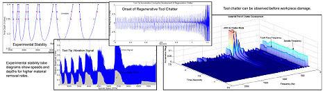 Figure 2. Tool-tip feedback determines end-milling cutting stability in real time (Click image for larger version) Figure 2. Tool-tip feedback determines end-milling cutting stability in real time (Click image for larger version) |
By capturing data on chatter frequency, the sensor can send feedback to the machine controller to change the cutting spindle speed and attenuate the phase difference between the metal surface and tool vibrations. Figure 2 also shows a stability diagram that defines allowable depth of cut vs. spindle speed in RPMs. With information obtained by the smart-tool sensors, you can recompute the diagram during cutting. The advent of sensor-enabled tooling opens the door for more accurate physical modeling of tool-tip dynamic processes.
Smart Tools vs. Traditional Machining Sensors
To attract the interest of the machining community, Suprock quantified the benefits of using a wireless sensor-enabled tooling system. Data obtained from the tool tip during the cutting process showed a cleaner signal, free of dynamic effects and bandwidth limitations. Effects such as mass loading on a dynamometer or the directionality of a spindle-mounted sensor were eliminated.
Figure 3 shows a comparison between the clarity of a traditional bed-mount force dynamometer and a wireless acceleration sensor. As shown, the force dynamometer has lower bandwidth and contains higher noise than the tool-tip signal of the wireless device.
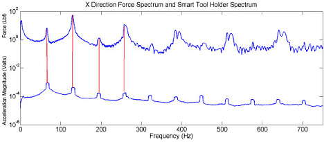 Figure 3.Smart tool vibration vs. bed force dynamometer (Click image for larger version) Figure 3.Smart tool vibration vs. bed force dynamometer (Click image for larger version) |
In addition to the force values from the bed dynamometer, Suprock also collected spindle power data at 20 kHz. Figure 4 shows output from both the wireless torque sensor and the spindle-power load cell. The graph shows that the power sensor has lower dynamic bandwidth than the wireless torque sensor. The company oversampled the power sensor to expose the large amount of high-frequency noise present in its signal. The superiority of the wireless torque sensor signal to the power sensor is apparent in both resolution and SNR. Because the torque is sampled directly at the tool, the wireless sensor eliminates the need to calculate motor efficiency and system losses (bearing tare power).
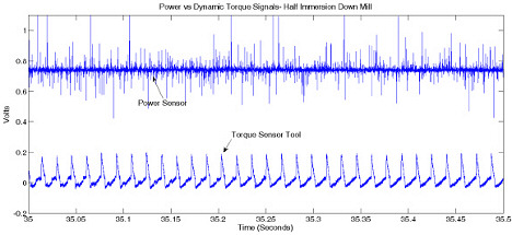 Figure 4. Dynamic torque vs. power sensor (Click image for larger version) Figure 4. Dynamic torque vs. power sensor (Click image for larger version) |
Conclusion
The future of metal-cutting feedback, especially for rotating cutting, such as end milling, will involve implementations integrating wireless sensors with tooling. Moreover, as production costs become higher, the metal-cutting industry will seek better feedback mechanisms to characterize and optimize its processes. Observing dynamics from within the tool itself provides the resolution necessary to make smart decisions about how to change the cutting process parameters.
It's time to break down the communication barrier between machining science and sensor design. Tomorrow's cutting tool will be a mix of mechanical tools and wireless sensors.
| A Barrier to Sensor Machine Tool Integration While neither the sensor-development nor machine-tool communities are at fault, an obstacle to progress is the lack of communication between the two fields. You can better understand this stumbling block simply by asking a machining scientist and an electrical engineer to define high bandwidth. Their answers will differ by a few orders of magnitude. |