Magnetic Sensors and Timing Applications

Fuel efficiency, emission control, and improved precision in machine control have become high priorities in engineering design. Advanced computers and sophisticated software algorithms are valuable tools, but a computer can perform amazing feats only when it receives accurate feedback from the mechanical system it is trying to control. The objective of a sensing system used in timing applications is to provide an electrical signal that accurately corresponds to the physical object being monitored. Magnetic sensors such as Hall effect and magnetic pickups are candidates for this job. Each, however, must be evaluated for its ability to satisfy the particular requirements of the application.

The four types of sensor discussed in this article are:

  • Variable reluctance (V/R) sensors with zero cross detection
  • Single-element Hall effect sensors with zero cross detection
  • Zero speed, differential Hall effect sensors with offset level detection
  • Differential Hall effect sensors with dynamic peak detection

Variable Reluctance
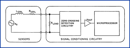
A V/R sensor or "mag pickup" is basically a small generator that produces an analog voltage proportional to the size and speed of a ferromagnetic target passing in front of the sensor. The output voltage has an inherent characteristic that is ideal for certain types of timing applications. The V/R sensor consists of a coil, a pole piece, and a magnet; its equivalent electrical schematic is shown in Figure 1.

Figure 1.

Figure 1. The variable reluctance sensor has an equivalent electrical circuit consisting of a voltage generator eg, the coil inductance LCOIL, and the resistance of the coil wire RCOIL. The output is an AC voltage with amplitude and frequency proportional to target speed. In this application, the AC voltage is converted to a digital signal using a zero cross detection circuit and passed to the controller's microprocessor.

The open circuit voltage, eg, is proportional to the number of turns of the coil and the rate of change of the magnetic field:

   eg = n • dF / dt

where:

   n = number of turns in the coil
   dF = rate of change in magnetic flux
   dt = rate of change in time

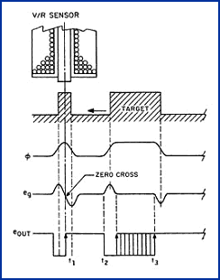
Figure 2 illustrates the voltage waveforms generated when a target passes in front of the sensor. The first tooth in the target profile has a width approximately that of the diameter of the sensor pole

Figure 2.

Figure 2. The changing field f caused by the moving target generates a voltage eg in the sensor coil that is proportional to the magnetic field's rate of change. For a small tooth, the digital output changes state when eg crosses through zero and creates a precise timing signal t1 coincident with the centerline of the sensor pole piece; for a larger tooth, however, the zero cross point can occur at any point between t2 and t3.
piece; the second tooth is much wider. The magnetic flux increases as the target passes in front of the sensor and decreases as the tooth passes by. Because the output voltage eg is proportional to the flux differential with respect to the change in time, it will first go positive as dF increases and then rapidly swing negative as the dF slope changes from positive to negative. The output voltage will return to zero when dF returns to zero.

In the case of the smaller tooth, voltage eg passes through zero at a point that is coincident with the center of the tooth. A digital output signal with a positive transition occurring at this point can be generated using standard zero cross detection circuitry. The wider tooth profile shown in Figure 2, however, has an unpredictable zero cross point that could produce a timing signal occurring at any point between t2 and t3 and therefore would not be suitable for timing applications. This inherent zero cross characteristic of a V/R sensor works well for timing applications as long as the target tooth width is close to the diameter of the sensor pole piece. This ideal timing signal at zero cross occurs only when there is minimal or no electrical load on the sensor. With a resistive load, the inductance of the sensor coil will cause the current in the circuit to lag the open circuit generator voltage and create a phase shift in the output voltage or timing signal:

   f = tan-1 [(2pfLCOIL) / (RLOAD + RCOIL)

where:

   f    = phase shift
   f    = frequency of output signal
   LCOIL = inductance of sensor coil
   RLOAD = load resistance
   RCOIL = resistance of sensor coil

This effect can be minimized by incorporating a signal conditioning circuit that has a relatively high input impedance. Where lower load impedances are required, the phase shift must be compensated in the postprocessing electronics. This is a relatively easy task because the phase shift is proportional to the speed and very predictable. For timing applications where the tooth size can be kept close to that of the sensor pole piece diameter, the V/R sensor is an excellent choice. It is not suitable, however, for applications requiring complex or multiple-width target profiles.

Single-Element Hall Effect Sensors
with Zero Cross Detection

This type of sensor produces a digital output signal that closely replicates the target profile. A
Figure 3.

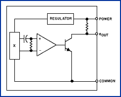
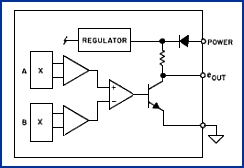
Figure 3. This single-element Hall effect sensor includes a voltage regulator, a single-element linear Hall effect device, a voltage comparator, and an output transistor. The output of the Hall effect device is AC coupled to remove the large DC offset voltage caused by the sensor's internal magnet.
single Hall effect element in the front of the sensor, back biased with a permanent magnet, is the source of the basic electrical signal. An equivalent electrical schematic of this type of sensor is shown in Figure 3.

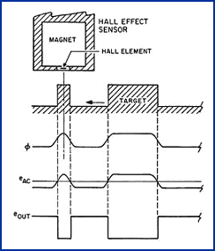
The Hall effect sensor generates a voltage proportional to the magnetic field flowing through it. As the target passes by the Hall element, the magnetic field through the element will vary in relation to the target profile (see Figure 4). The Hall element will generate a small electrical voltage proportional to the changing flux. This signal is superimposed on the large DC voltage created by the fixed field from the magnet and must be run through a high-pass filter (standard AC coupling) to remove the large DC offset voltage. The resulting signal is a small AC voltage that swings above and below a

Figure 4.

Figure 4. The single-element Hall effect device is precisely located on the centerline of the sensor and is back biased with a strong magnet. The magnetic field intensity through the Hall device changes in relation to the target profile and creates a voltage that is directly proportional. The AC signal is converted to a digital output that closely replicates the target profile.
zero reference level. A high-gain comparator converts the voltage to a digital signal that closely follows the target profile. The disadvantage of the high-pass filter is that it requires time to stabilize after power has been applied to the sensor. In contrast to V/R sensors, Hall effect devices do not have significant phase shifts due to "storage" elements in their design and are therefore usable over a wide speed range without requiring speed-sensitive compensation techniques.

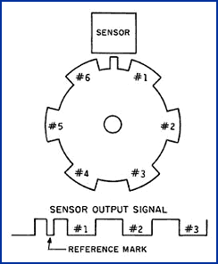
This type of sensor has a significant advantage in applications where unique target profiles provide different types of positioning information to the computer. For example, a narrow tooth in the target wheel could provide a reference mark for the crankshaft position, and the piston positions could be determined with wider, evenly spaced teeth (see Figure 5). In a V/R sensing system, two sensors and a dual target configuration would be required to obtain the same information.

Zero Speed, Differential Hall Effect
Sensors with Fixed Operate and
Release Points

Figure 5.

Figure 5. Because the single-element Hall effect sensor replicates the target profile, complex target wheel configurations can be created to generate unique signatures. The target wheel shown here includes a narrow pulse that can easily be distinguished from the wider pulses to provide a top dead center mark for engine timing.
This type of device, commonly called a zero speed gear tooth sensor, incorporates dual Hall effect sensing elements configured in a differential mode (see Figure 6). Probably the simplest type of all the Hall effect sensors, it is widely used for speed detection. Although extremely effective when counting teeth is the primary objective, converting the differential output from the Hall elements to a digital output can create unpredictable results for some timing applications.

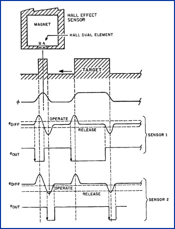
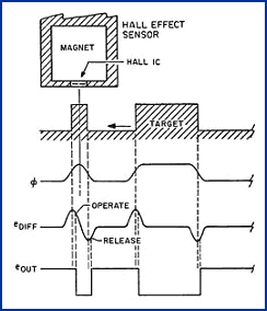
The signal, eDIFF, is the voltage difference between Hall elements A and B (see Figure 7, below). This voltage is compared to a couple of fixed thresholds that establish the operate and release points of the signal. Notice that sensor 1 in the diagram has operate and release points evenly spaced above and below the nominal differential signal voltage. When eDIFF exceeds the operate point, the digital

Figure 6.

Figure 6. The zero speed Hall effect sensor incorporates two linear Hall generators whose outputs are subtracted from each other to provide a differential signal that eliminates the DC bias offset effects. A differential output signal is created when the target passes by the two elements.
output changes state and stays there until the signal drops below the release point. Although the output signal follows the profile of the target, it leads the actual profile by a significant amount. If this were a fixed amount, it could be compensated; because the two Hall devices are not always balanced, however, the differential output voltage could be offset as much as that shown in Figure 7's sensor 2. Although sensor 2 meets the same vendor specifications as sensor 1, the digital output, eOUT, is dramatically different from that of sensor 1. This sensor should be considered for only those timing applications in which the operate and release points are certain to remain equally above and below the nominal eDIFF level. It should also be noted that because the sensor is a differential device, it must be oriented with respect to target travel.

Figure 7.

Figure 7. The timing diagram shown here for a zero speed sensor using the differential Hall effect concept illustrates the way that two "like" sensors can generate very different output timing signals. Sensors 1 and 2 are the same except for the operate and release points, which can dramatically affect the location where the output changes state.

Dynamic Peak-Detecting
Differential Hall Sensors

This type of sensor is based on a dual-element, differential Hall effect technology similar to the zero

Figure 8.

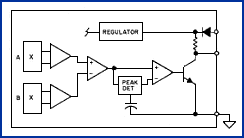
Figure 8. This sensor is very similar to the zero speed sensor except that it uses a dynamic peak-detecting scheme to provide a switch point that occurs at the peaks of the differential signal. This technique eliminates the variability associated with the zero speed sensor, but it has a lower frequency cutoff point and will not operate at zero speeds.
speed sensor, but it uses a totally different signal detection scheme that eliminates the problems incurred with fixed-level operate and release switch point devices. The electrical equivalent schematic for this type of sensor is shown in Figure 8.

This technique, relatively new on the market, is inherently well suited for timing applications. The differential voltage eDIFF is the same as with the zero speed, differential Hall sensor but the detection method is not (see Figure 9). Instead of having fixed operate and release points, this sensor is referenced to the peak levels of the incoming signal. The reference points are just below the peak level and are dynamically updated with a track-and-hold circuit. When the input signal level

Figure 9.

Figure 9. The switch points for the peak-detecting dual differential Hall sensor shown here occur at the peaks of the differential output signal. Since the peaks are coincident with the edges of the target profile, the digital output signal from this type of sensor provides a very accurate timing signal that is capable of replicating complex target wheel profiles.
drops just below the peak level, the output changes state, thereby creating a switch transition coincident with the peak of the differential voltage from the sensor. The peaks of the signal occur very close to the edges of the target profile, so the resulting output signal is an electrical replication of the target profile.

Summary
Understanding the operating principles of the various candidate sensors is an important first step toward selecting the right device for a timing application, but attention must be paid as well to many other considerations such as overall costs, mechanical packaging, installation requirements, and environmental conditions before making the final choice.