
This article presents both a brief explanation of hazardous location requirements and an attempt to unravel the codes used to identify them. It is not intended for engineers designing the actual electrical equipment, but rather for those who need enough basic information to properly interpret and specify the right electrical equipment for installation on their machinery.
 |
Division and Zone Systems
There are two basic systems for classifying hazardous locations and equipment requirements. The Division system has been used in the U.S. and Canada for many years and is defined in the National Electrical Code (NEC) Article 500 and the Canadian Electrical Code (C22.2).
Figure 1. Likelihood of Hazardous Atmosphere |
The international, or Zone, system, based on International Electrotechnical Commission IEC 60079 specifications, has been adopted and modified by a number of organizations including the Canadian Standards Association (C.S.A.), Atmosphere Explosive (ATEX), and NEC Article 505. It is gaining popularity in all parts of the world including the U.S. and Canada. In Canada, all new installations must be classified using this approach.
Figure 2: Gas Groups |
Area Classifications
Hazardous locations can contain gas, dust (e.g., grain, metal, wood, or coal) or flying fibers (textiles or wood products). Hazardous gas locations are by far the most commonly studied, primarily due to the petroleum process industry, and will be our focus here.
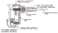 Figure 3. To satisfy the Flameproof requirements, an apparatus must be housed in such a way as to contain internal explosions and to prevent their igniting external gases. |
Likelihood of Presence
Hazardous locations are broken down in several different ways. The first is by the likelihood of a hazard's being present. In the Division system, this is separated into two divisions; in the Zone system, it is segmented into three (see Figure 1).
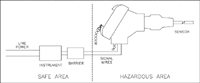 Figure 4. An Intrinsically Safe device must not store enough electrical energy to ignite its ambient atmosphere. A safety barrier is therefore required that under a fault condition limits the voltage and current to safe levels. |
The Zone system basically takes Division 1, splits it in two, and then segregates the most hazardous locations into a third segment, Zone 0. Doing so allows the requirements for equipment used in the more common Zone 1 locations to be less restrictive. This can save a lot of time and money in Zone 1 installations and is the major reason the Zone system is gaining popularity.
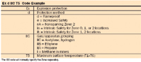 Figure 5(A): Example (IEC 60079 and CSA E60079): |
Gas Groups
Both systems divide the areas by the types of gas that are or may be present. The more easily ignitable the gas, the tougher the requirements, and acetylene and hydrogen are at the top of the list (see Figure 2). Groups C and D in the Division system and Groups IIA and IIB in the Zone system are by far the most common, again due to connections to the oil process industry.
Surface Temperature Classification
Auto-ignition temperature is the temperature at which a particular gas will ignite without a spark. You don't want the surface temperature of your apparatus higher than the auto-ignition temperature of the gas it might encounter. Temperature classes take this into account by assigning codes ranging from T1 = 450ºC (842ºF) to T6 = 85ºC (185ºF). The temperature listed refers to the maximum degrees the surface of the apparatus may attain due to heating of the internal electrical components. Surface temperature classes are based on a maximum ambient of 40ºC (104ºF) unless otherwise specified, so if you are working with higher ambients, you need to keep this in mind. These classifications apply to both Divisional and Zone concepts.
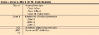 Figure 5(B): U.S. variant (NEC Article 505) example: |
Protection Methods
Flameproof or Explosionproof. Flame-proof is a Zone system term; explosionproof is used in the Division system. The terms are often used interchangeably, and refer to the same concept—to construct the apparatus enclosure to withstand any explosion that might occur inside it and prevent that explosion from igniting a possible surrounding hazardous atmosphere. It's generally characterized by a thick-walled enclosure with long, tight-fitting, flame propagation paths (see Figure 3). Appropriate for Division 1 and 2 and Zone 1 and 2 locations, this solution is the oldest method of protection and is still very popular. A major disadvantage is that the wiring methods are expensive, requiring special cables and fittings, or, in the case of North America, rigid conduit. It can be used for circuits that require high power.
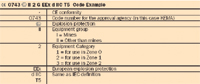 Figure 5(C): E.U. variant (ATEX) example: |
Intrinsically Safe or Intrinsic Safety. This method requires an apparatus electrically designed to preclude its generating or storing enough energy to ignite a hazardous atmosphere. It must be used in circuits containing an intrinsic safety barrier that under normal operating conditions will allow the apparatus to operate normally, but under a fault condition limits the voltage and current delivered to the circuit to safe levels. It can be used in Division 1 and 2 and in Zone 0, 1, and 2 locations, and is considered the safest protection method. The advantage here is that it requires only a few modifications to standard field wiring. The disadvantages are that it can't be used for circuits that require high power, and that the circuit must run through a special barrier located in a safe area such as a pressurized control booth or explosionproof enclosure (see Figure 4).
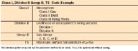 Figure 5(D): Division System: Canadian Electrical Code (C22.2 and NEC article 500) |
Nonsparking. As the name implies, this technique does not work for an apparatus that can cause a spark (e.g., relays and switches) unless it is sealed in some way; it is therefore allowed only in Zone 2 locations where the chance of a hazardous atmosphere's presence is small. The advantages are that the manufacturer can self-certify, making the apparatus cheaper for the end user; it's also very easy to meet requirements with many nonsparking devices such as temperature sensors. Among the disadvantages are its restriction to Zone 2 locations and its lack of recognition by the Division system.
Nonincendive. This is similar to the Zone's Nonsparking method. It does allow contacts, but only if they are "constructed so they are incapable of igniting the hazardous atmosphere." It's suitable for Division 2 locations only, and very useful for circuits that contain only passive apparatus such as RTDs or thermocouples since they can be used in nonincendive circuits with standard enclosures. This method is not recognized in the Zone system and again is suitable only for low-power circuits.
Other, less popular protection approaches include encapsulation, oil immersion, powder-filled, and pressurized techniques.
Simple Apparatus. This concept applies to RTDs and other passive devices, and low-power-generators such as thermocouples. Because these units are inherently incapable of generating or storing enough electrical energy to ignite a hazardous atmosphere, when used in an intrinsic safety circuit they require neither approval nor special marking. The Simple Apparatus concept is recognized by all the approval authorities, and may allow you to use relatively inexpensive standard components.
Code Types
The IEC specifications code is the basis for most international requirements. Canada has adopted these standards pretty much to the letter. The U.S., in National Electrical Code (NEC) Article 505, has modified it somewhat, as has the E.U. with its CENELEC and ATEX standards. The IEC designations and their variants are given in Figure 5(A, B, C, and D).
Where to Go for Help
Here's a handy list of standards and their supporting organizations:
- 1. National Electrical Code (NEC) Articles 500 and 505, available from the National Fire Protection Agency (www.nfpa.org|~www.nfpa.org/ ) and many bookstores. More specific standards are written by and available through approval agencies such as Factory Mutual (www.fmglobal.com|~www.fmglobal.com/ ) and/or Underwriters Laboratory (www.ul.com|~www.ul.com/ ).
- 2. IEC Standards (www.iec.ch/|~www.iec.ch/ )
- 3. CENELEC (European Committee for Electrotechnical Standardization, www.cenelec.org|~www.cenelec.org/ )
- 4. ATEX Standards (europa.eu.int/comm/enterprise/atex)
- 5. Canadian Electrical Code (CEC, www.csa.ca|~www.csa.ca/ )
Both Factory Mutual and CSA offer seminars on the subject. They are usually two- or three-day in-depth classes that are highly recommended. The presenters are well-versed in the subject and can answer most questions or put you in touch with someone who can. They cover all the protection methods and discuss both U.S. and international standards. Seminar information is available on their Web sites, and they frequently offer the classes around the country at various times of the year. You could also visit www.minco.com/e2e, Minco's engineer-to-engineer online discussion forum and Ask the Experts section.
An understanding of hazardous location requirements and codes will give you an appreciation of the parameters involved in designing a facility where the risk of explosions and fires must be taken into account. It will also help you to properly interpret and specify the correct electrical equipment to order from your equipment manufacturer.
Dave Wilson, B.S.E.E., can be reached at Minco, Minneapolis, MN; 763-586-2872, [email protected], www.minco.com.