
|
Piezoelectric motors have been around for years, but acceptance has been slow because they were relatively expensive. However, recent advances have significantly reduced the channel cost of this technology for closed-loop systems that require high positioning accuracy. With the use of a wide range of PID controllers and/or position sensors, the list of piezoelectric motor product applications is growing daily (see "Piezoelectric Motor Applications?).
|
Today, modern polycrystalline piezoelectric ceramic is mass-produced for applications including underwater transducers, point level sensors, medical products, ultrasonic cleaners, actuators, fish finders, and motors. High-purity lead, zirconate, and titanate powders are processed, pressed to shape, fired, electroded, polarized, and tested. Polarization is achieved using high electric fields (2500 V/ mm) to align material domains along a primary axis (see Figure 1).
 Figure 1. High electrical fields are used to polarize ceramic materials. Once domains are properly aligned, the piezoelectric material can do useful work. |
|
In Figure 2, a 200 V charge is applied to a piezoelectric crystal with a displacement constant (d33) equal to 500 pm/ V. This produces an axial displacement of 0.1 microns, a fairly small number that could be good or bad depending on the application. It is very repeatable and lasts a lifetime with a properly designed drive circuit, but the motor will not travel very far when 200 V are applied just once every second. This is the reason piezoelectric motors are driven at or near a resonant frequency mode of the crystal shape.
|
In the example shown in Figure 3, a simple standing wave is generated in a thickness-mode piezoelectric crystal to produce linear motion (U.S. Patent No. 4,622,483). Other piezoelectric motors may use shear, hoop, or planar vibration modes for motion, as called for by the application. Sophisticated designs that provide exceptional performance are possible, but at an increased cost. For now, simpler is better.
Piezoelectric crystals are positioned in a simple mechanical motor arrangement and driven in their thickness direction to produce useful work—linear motion—as shown in Figure 4.
    |
Two piezoelectric crystals are preloaded against a flat wear surface, by way of the motor shoe, to produce a normal contact force. Friction is important here, since every piezoelectric motor needs friction to operate. As a "positive? sinusoidal voltage waveform:
| (1) |
drives the crystal to increase its thickness, the axial motion imparts a frictional force:
| (2) |
of ~ 2"3 N along the wear strip, moving it to the left.
When the sign of the drive voltage swings negative, the same crystal thickness contracts. This action creates a minuscule separation between the motor shoe and the wear strip, allowing the motor to return to its original position without dragging the wear strip backward. As the drive voltage swings positive again, the crystal stroke cycle repeats and the wear strip moves another incremental step to the left.
When the crystal driving process is repeated 130,000 times/s, with a resonant frequency amplification factor of 10, the resulting velocity is ~130 mm/s (5 ips) using mid-range control voltage. Faster or slower motor speeds are achieved by changing control (input) voltage (see Figure 5).
  Figure 5. Using simple drive circuits, motor speed and direction can be proportional to the magnitude and sign of the input control voltage (A). Many incremental motor steps determine motor position over time. Motor accuracy is also directly proportional to these incremental steps (B). |
|
Motor performance is enhanced with the strategic placement and use of additional piezoelectric crystals or structural elements. To meet additional force requirements, several motor elements may be driven in parallel. This process will cumulatively add force. For example, Figure 6B shows two crystals, working complementary to each other to provide twice the baseline motor force.
 |
 |
 |
 |
|
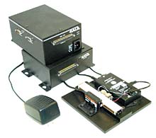
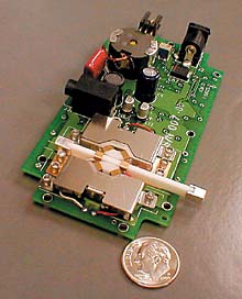
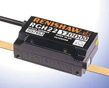
Closed-loop systems can track and control linear motions to small fractions of a micron. Photo 3 shows very low profile EDO piezoelectric motors driving a small stage with a top speed of 300 mm/s and a position capability of 0.1 micron. This system uses mature, commercially available hardware such as Galil's Model 1412 motion controller (Galil Motion Control Inc., Rocklin, CA), with public domain software, and the Model RGH22 noncontact position encoder from Renishaw (Hoffman Estates, IL) shown in Photo 4.
|
Reference
1. Kenji Uchino. 1997. Piezoelectric Actuators and Ultrasonic Motors, Kluwer Academic Publishers:269.