
 Figure 1. In a fiber-optic sensing system, the emitter and the receiver share a single housing. The fiber-optic cable that is connected to the amplifier allows the sensor to reach areas inaccessible to standard photoelectric sensors. |
The sensor emits, receives, and converts the light energy into an electrical signal. The cable is the mechanical component that transports the light into and out of areas that are either too space constrained or too hostile back to the sensor.
|
Glass Fibers
Optical fiber can be made of either glass or plastic. Glass optical fibers consist of a bundle of very thin glass strands, each typically measuring 0.051 mm (0.002 in.) dia. A flexible stainless steel–armored sheath is usually added to protect the bundle of cladded fibers, but for some applications a polyvinyl-chloride jacket (PVC) is used.
Glass, by nature, is very resilient, a trait that enables it to perform reliably under extreme conditions such as high temperatures or a corrosive environment. Glass fiber bundles can withstand operating temperatures as high as 450°F as standard product. Customers whose applications have operating temperatures >450°F can special-order cables capable of surviving operating temperatures as high as 1200°F.
With reasonable radius corners, glass fibers can withstand indefinite cyclic bending. Given this premise, you would think that glass fibers can stand up to sharp bending, stretching, extreme vibration, pulling, and other harsh treatment. But they can't. In fact, they tend to break, and while a few broken strands in a bundle are generally not noticeable, when large numbers are severed there will be a proportionate loss of signal strength.
To achieve a high degree of light-coupling efficiency, fiber manufacturers optically polish the surface of the sensing face to ensure that the end of each fiber is perfectly flat. We therefore encourage customers to special-order nonstandard cable lengths rather than trying to do their own cutting to size.
Plastic Fibers
Plastic fiber-optic cable usually consists of a single strand typically 0.254–1.52 mm dia. These fibers are flexible, and excellent for applications that require repeated flexing as well as for use in extremely tight areas. They generally are sold with a cutting device that allows customers to trim to the desired length.
In recent years, Omron and certain other manufacturers have released multi-core high-flex plastic fiber. These differ from conventional plastic fibers in having multiple independent cores, a configuration that allows a bending radius as small as 1 mm and thus a flexibility close to that of electric wire. They can be bent at 90° with no reduction of light transmission, and readily conform to machine contours without the problems associated with extreme vibrations or pulling. Various vendors also offer coiled versions of plastic fibers for applications that require articulated or reciprocating motions.
When the sensor will be exposed to harsh chemicals, solvents, or high temperatures, glass fibers are preferable. But plastic fibers can be sheathed with Teflon, nylon, or polypropylene for added immunity to hostile environments.
The degree to which light energy is attenuated as it travels through optical fiber is influenced by three factors: the fiber material, the distance traveled in the fiber, and the wavelength of the light. Glass fibers perform fairly consistently at all wavelengths. Plastic fibers, however, tend to absorb light from IR LEDs. Visible LEDs, such as red, exhibit less attenuation in plastic optical fiber and are therefore in wider use.
|
The complete transmission of light through fiber optics is based on the principle of total internal reflection, which states that all the light striking a boundary between two media will be totally reflected. That is, no light energy will ever be lost across the boundary. This principle pertains only when two conditions are met:
- The critical angle is less than the angle of incidence for the particular combination of materials (see Figure 3). The materials in this case are the core and the cladding of the optical fiber.
- The light is in the denser medium and approaching the less dense medium. The cladding material is less dense than the core material, and as a result has a lower index of refraction.
As long as these two conditions are satisfied, the principle of total internal reflection applies whether the fiber-optic cable is bent or straight (within a defined minimum bend radius).
Sensing Modes and Fiber-Optic Assemblies
Because fiber-optic sensor systems are a derivative of photoelectric sensing technology, photoelectric sensing modes (diffuse reflective, through-beam, retroreflective) are also available for fiber optics. The two types of fiber-optic assemblies that address these sensing modes are individual and bifurcated.
Fiber-optic through-beam mode, as shown in Figure 1, requires two cables. One is attached to the emitter of the remote sensor and is used to guide light energy to a sensing location. The other is attached to the receiver of the remote sensor and is used to guide light energy from the sensing location back to the remote sensor. As with standard through-beam photoelectric sensing, the emitter and detector cables are positioned opposite each other. Sensing is achieved when the light beam that extends from the emitter to the receiver fiber-optic cable is interrupted.
A bifurcated fiber-optic assembly is used for both diffuse reflective and retroreflective sensing. In constrast to an individual cable,
|
Benefits of Fiber Optics
Because optical fiber is essentially a passive, mechanical component of a fiber-optic sensing system, it contains neither moving parts nor electrical circuitry and is therefore completely immune to all forms of electrical interference. This characteristic makes it an ideal way to isolate the sensing system electronics (in this case the remote sensor to which it connects) from known sources of electrical interference.
Furthermore, there is no possibility of a spark, allowing its safe use even in the most hazardous sensing environments such as oil refineries, grain bins, mining operations, pharmaceutical manufacture, and chemical processing. There is also no danger of electrical shock to personnel repairing broken fibers.
Latest Developments
As industrial automation applications grow more complex, and real estate becomes more of a concern, there is a concomitant call for more sophisticated sensing devices in smaller packages. Omron, Keyence Corp. of America (Woodcliff Lake, NJ), Banner Engineering Corp. (Minneapolis, MN), and SUNX Sensors (West Des Moines, IA), among others, have begun to respond by introducing new waves of fiber-optic sensors.
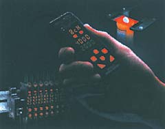
These companies now offer fiber-optic amplifiers (remote sensors) with easy-to-read digital LEDs. The numerical values and percentages that are displayed allow users to monitor and precisely set up their applications. The digital display provides real-time feedback that advises of the slightest misalignment, or of dust accumulation on the cable tip that is beginning to degrade sensor performance.
|
New dual-output fiber-optic sensors offer the performance of two sensors in one package. Certain models offer either two independent digital outputs or a combination of analog and digital output. Other types also have a "lockout" feature that prevents unwanted adjustments of or tampering with the sensor's settings. This feature allows customers to give their employees on the shop floor a degree of autonomy without compromising their performance goals.
Most of these sensors now incorporate either a 12-bit or 16-bit CPU as well as 12-bit A/D converter that provides both higher resolution and faster response time, in some cases as fast as 20 µs. As many as four auto-teach functions enable quick sensor setup and allow the user to select the best teach method for the application.
|
With all the flexibility and benefits that fiber-optic sensor systems provide, it is no wonder that they are becoming more widely used. As industrial automation applications continue to become more sophisticated, expect sensor experts to continue developing innovative fiber-optic sensors.