
Traditional inductive position sensors
Traditional inductive position sensors have a 70 year track record of safe, reliable and accurate operation in harsh environments. Such conditions are commonly found heavily in industrial, aerospace, defense and petrochemical sectors. In large part, inductive sensing’s reputation comes from the technique’s fundamental physics which is largely insensitive to temperature, vibration, lifetime and foreign matter. It’s no coincidence that inductive position sensors are chosen by (notoriously conservative) design engineers for military and civil aircraft applications rather than the more delicate optical, magnetic or capacitive alternatives. A modern passenger jet might use >100 inductive position sensors for motion control of its flight surfaces, fuel flow, undercarriage and pilot controls.

Traditional inductive sensors come in lots of shapes, sizes and formats. Inductive rotary sensors are usually synchros, resolvers or RVDTs (rotationally variable differential transformers) and the linear form is most usually a LVDT (linearly variable differential transformer) and occasionally a variable reluctance transducer. The most common is the resolver for rotary measurement and LVDT for linear measurement.
Most inductive proximity sensors typically have a simple digital output, usually indicating the presence or absence of a metal target. Pedantically, they should really be termed inductive proximity switches and although they might be used for simple, low resolution position measurement they are not the subject of this paper. Instead, this paper focuses on continuous measurement of displacement along a rotary or linear axis.
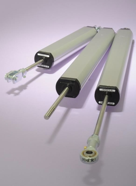
LVDTs - Still Popular For Civil and Military Aircraft
Traditional inductive position sensors all use the same basic construction – wire spools or windings in a transformer arrangement. The transformer’s primary windings are energized with an AC signal of 1-10kHz and as one element of the transformer displaces relative to the others, it causes a change in the inductive coupling between the primary and secondary windings. In turn, this changes the output from the transformer’s secondary windings and the ratio of these signals is proportional to displacement.
The non-contact, electromagnetic operation of inductive position sensors means they are largely insensitive to temperature, foreign matter or lifetime effects. The ratiometric technique also provides a low temperature coefficient (or thermal drift) because although the signal from one winding might vary significantly with temperature, the ratio of multiple signals will not.
Inductive Position Sensors For Safety Applications
In most safety applications, the overriding concern for a position sensor is that it should fail safe. In other words, in the event of a failure, the position sensor should not report an incorrect position because such a failure could lead to catastrophic consequences. Instead, in the event of a failure, it should provide an invalid and hence safe output.
Inductive position sensors can be considered by a design or safety engineer as providing a robust mitigation of failure modes. This is due to their fundamental physics and the ratiometric approach. With an inductive position sensor, such as a resolver or LVDT, analysis of its failure modes will show that if one element of the sensor fails it does not necessarily produce an incorrect output. Instead, if one element fails, the sensor is much more likely to produce an invalid – or safe - result.
Naturally, the question arises why traditional inductive position sensors are not more widely used. The answer is simple – they are too bulky and too expensive for most applications.
Inductively resonant position sensors
Inductively resonant position sensors are increasingly being chosen over their traditional alternatives, because they are less bulky, more accurate and less costly. Although resonant inductive position sensing has not been around as long, it has gained a reputation for reliability in difficult applications – most notably in the medical, military and petrochemical sectors. To date there have only been a few successful aerospace applications, but this is now forecast to change quickly because of the sizeable weight advantage.
Inductively resonant sensors use the same fundamental physics and the same ratiometric technique as a resolver or LVDT but rather than wound transformer constructions they use printed circuits as their main sensing elements. They also use much higher frequencies than traditional inductive sensors, as well as a resonant technique. This means that the sensor’s primary and secondary windings as well as the moving target all operate at a specific, resonant frequency. This electrical resonance helps amplify the otherwise lows signals that would come from the circuit board arrangement.
The same basic physics produces the same advantages – reliable and accurate sensing in harsh environments, with failure modes which are particularly suitable for safety related applications.
This new type of sensor is often referred to as an incoder – from combining inductive and encoder. Whilst incoders use the same physics as a traditional inductive sensor they have the same, simple electrical interface as an optical encoder: - a DC supply and a digital output signal. Accordingly, they are easier to specify and use; more accurate; but just as robust as their bigger, heaver, traditional cousins.
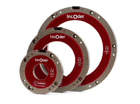
Inductive Encoders Offer Reliable Measurement In Harsh Environments
Incoders typically use energization and signal conversion electronics adjacent to their primary and secondary windings. However, as with their traditional counterparts the electronics need not be directly adjacent.
This is particularly useful in displacing the electronics away from the very harshest of conditions where the electronic components might otherwise limit the operating envelope. The only significant advantage that traditional inductive sensors have is that the electronics maybe displaced further away than with the inductively resonant approach.
Zettlex UK Ltd,
Cambridge, United Kingdom
+44 1223 874444