
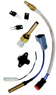
in this article can be packaged to suit the
application. These packages are variously used
for immersion and surface sensing, including
subminiature versions for PCB environments.
After briefly reviewing how RTDs, IC sensors, thermistors, and thermocouples are constructed and used to measure temperature, we discuss what differentiates these sensors from one another. We address temperature range, tolerance, accuracy, interchangeability, and relative strengths and weaknesses for each type. Our intention is to give the readers a better understanding of when to use each type of sensor and why.
Review of Thermal Sensing Technology Basics
RTDs. These devices contain a metal sensing element, which is an electrical resistor that changes resistance with temperature. This change in resistance is well understood and is repeatable. The sensing element in an RTD usually contains either a coil of wire or a grid of conductive film that has a conductor pattern cut into it (see Figure 1).
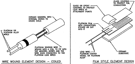
both use platinum as the sensing element because of its predictability as a resistor.
Extension wires attached to the sensing element allow its electrical resistance to be measured from some distance away. The sensing element is then packaged such that it can be placed into a position in the process where it will reach the same temperature that exists in that process (see Figure 2).
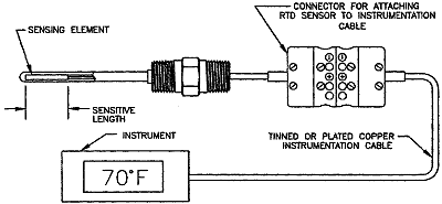
as quickly as possible. The probe design shown here is a good configuration for immersion applications.
IC Sensors. IC sensors take advantage of the variable resistance properties of semiconductor materials. They provide a linear voltage or current output, especially at low temperatures. These devices can provide a direct temperature reading in digital form, thus eliminating the need for an A/D converter. Because IC sensors can have memory, they can be very accurately calibrated, and may operate in multisensor environments in applications such as communications networks.
Thermistors. Thermistors (a contraction of thermally sensitive resistors) also correlate temperature with resistance. In contrast to RTDs, thermistors are based on an element made of a semiconducting material that typically consists of a mixture of metal oxides. This construction results in significantly higher sensitivity to changes in temperature than is characteristic of RTDs (many ohms per degree vs. tenths of an ohm per degree with RTDs). Since thermistors do not contain expensive metals such as platinum, they can offer significant cost advantages over RTDs. However, because their resistance vs. temperature characteristics are nonlinear, thermistors are typically used to measure temperature in narrow temperature ranges so that the nonlinearity can be minimized. Thermistors also have a narrower operating temperature range than RTDs or thermocouples.
Thermistors are packaged into sensor configurations that are similar to those used for RTDs, and into special sensor configurations that take advantage of their small size and low mass to maximize response time in air. There are two basic types of thermistor: positive temperature coefficient (PTC), which exhibit an increase in resistance as temperature rises, and negative temperature coefficient (NTC), whose resistance decreases with increasing temperature.
Thermocouples. Thermocouples incorporate two electrical conductors made of different materials that are connected at one end. The end of the conductor that will be exposed to the process temperature is called the measurement junction. The other end (usually where the conductors connect to the measurement device) is called the reference junction (see Figure 3.
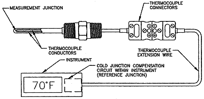
higher temperature applications but they are less table over the long term.
When the measurement and reference junctions of a thermocouple are at different temperatures, a millivolt potential is formed in the conductors. Knowing the type of thermocouple used, the magnitude of its millivolt potential, and the temperature of the reference junction allows the user to determine the temperature at the measurement junction.
The millivolt potential created in the thermocouple conductors is a function of the materials of construction. Some materials make better thermocouples than others because the millivolt potentials they create are more repeatable and well established. These thermocouples have been given specific type designations including Types E, J, K, N, T, B, R, and S. The ways in which these devices differ from one another will be explained later.
Temperature Limitations for Thermal Sensing Devices
The materials used in thermal sensing devices have temperature limitations that can be an important consideration in their use.
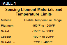 RTDs. As stated earlier, an RTD consists of a sensing element, wires to connect the element to the measurement instrument, and some kind of support to position the element in the process. Each of these materials sets limits on the temperature to which the RTD can be exposed.
The sensing element usually contains a platinum wire or film, a ceramic housing, and ceramic cement or glass to seal the element and support the element wire. Generally speaking, platinum sensing elements can be exposed to temperatures up to ~1200°F. Other materials such as nickel, copper, and a nickel/iron alloy can also be used, but their useful temperature ranges are quite a bit lower than platinum's (see Table 1).
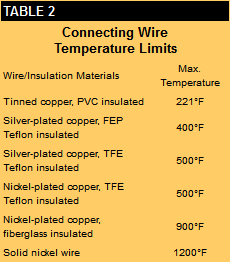
The wires that connect the sensing element to the readout or control instrumentation are usually made of materials such as nickel, nickel alloys, tinned copper, silver-plated copper, or nickel-plated copper. The wire insulation also directly influences the temperature to which the RTD can be exposed. Table 2 lists the most common wire and insulation materials and their maximum operating temperatures.
Placing the sensing element into the process also requires careful materials selection. The most common method is to insert the sensing element and attached wires into a closed-ended metal tube, pack the tube with a vibration damping and/or heat transfer material such as ceramic powder, and seal the open end of the tube with an epoxy or ceramic cement. The metal tubes most commonly used for RTDs are made of stainless steel (used to ~900°F) or Inconel (to ~1200°F). The vibration damping/heat transfer materials vary widely in temperature range, and are selected by the manufacturer to provide the optimum performance based on the maximum expected operating temperature. Epoxy sealing compounds are typically never used above 400°F-500°F. Ceramic cements can be exposed to temperatures 2000°F, but require sealants to keep moisture out of the cement and the underlying vibration damping/heat transfer material.
The material with the lowest temperature capability in a platinum RTD is usually the wire and insulation connecting the sensing element to the instrumentation. Manufacturers typically offer two constructions-low temperature and high temperature. In low-temperature constructions, Teflon-insulated nickel or silver-plated copper wire is used along with an epoxy seal. This construction is usually limited to 400°F-500°F.
High-temperature constructions typically use fiberglass-insulated, nickel-plated copper wire and a ceramic cement that has a maximum temperature of 900°F-1200°F. Some manufacturers also offer a line of RTDs that use a ceramic-insulated nickel or nickel alloy wire for use up to 1200°F.
IC Sensors. The electrical resistance of silicon also changes with temperature. Since these sensors are based on a silicon semiconductor, their useful temperature limits are typically on the order of -55°C to 150°C. IC sensors can be assembled into immersion packages similar to those used in thermistors or RTDs, but can also be PC board or surface mounted.
Thermistors. Thermistors typically consist of lead wires soldered to a semiconductor wafer or chip. The wafer and connections are usually covered with epoxy or glass. Due to the materials used, thermistors are normally rated for use over a range of -100°C to 300°C. PTC-type thermistors have a positive temperature coefficient for only a portion of their temperature range, so they are limited to a much smaller useful range than NTC-type thermistors.
Because thermistor elements are often rather small, a millimeter or two, they can be used in a wide variety of thermal sensing packages. Immersion sensors are generally used to position the thermistor element into a medium such as air, water, fuels, or coolants. In some air applications, the thermistor element may be directly exposed to the air. In other applications, the element is packaged in a sealed tube or housing to protect it from the medium. Since the thermistor element's operating temperature is lower than that of RTDs, the materials of construction are generally of lower temperature capability.
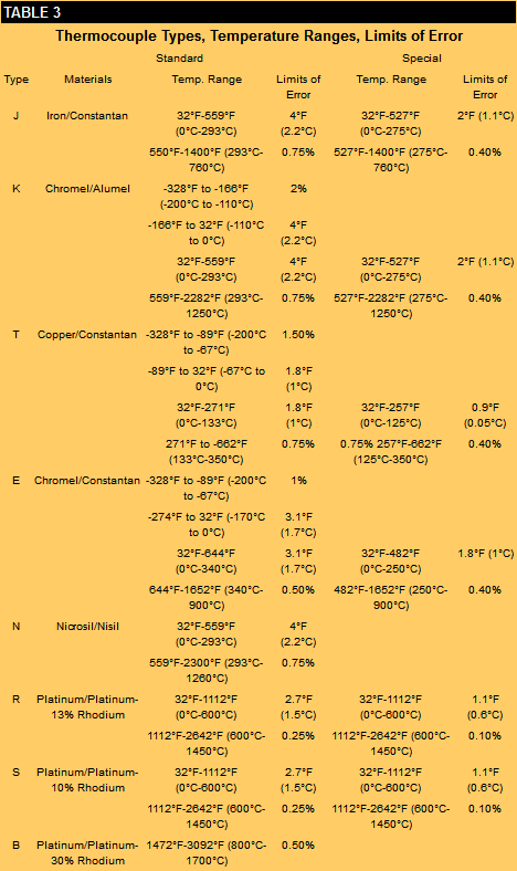
Thermocouples. Thermocouple materials are available in Types E, J, K, N, T, R, S, and B. They can be divided into two groups: base metal and noble metal. Types E, J, K, N, and T are known as base metal because they are made of common materials such as copper, nickel, aluminum, iron, chromium, and silicon. Each has preferred operating conditions; bare Type J units (iron/constantan), for example, are typically limited to a maximum temperature of 1000°F and are not recommended for use in oxidizing or sulfurous atmospherýs that would degrade the iron conductor. Bare Type T thermocouples (copper/constantan) are not used above 700°F because the copper conductor would deteriorate. Temperature ranges for these are included in Table 3, and additional application information is given in Table 4.
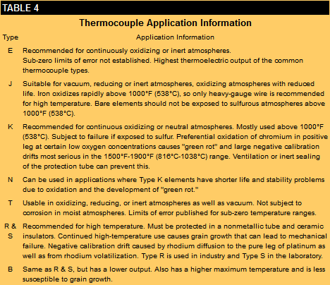
Types R, S, and B thermocouples are known as noble metal thermocouples because they are made of platinum and rhodium. They are used in applications that exceed the capabilities of base metal thermocouples. Types R and S are rated for use at temperatures between 1000°F and 2700°F; Type B is rated from 1000°F to 3100°F. When long-term exposure at temperatures >2500°F is expected, it is prudent to specify Type B for improved thermocouple life. Types R and S can experience significant grain growth if held near their upper use limit for long periods of time.
Since thermocouples do not have sensing elements, they are less limited than RTDs by the materials of construction. Thermocouples are normally built around bare conductors that are then insulated in a compacted ceramic powder or in formed ceramic insulators. This construction allows thermocouples to be used at much higher temperatures than RTDs can handle.
Tolerance, Accuracy, and Interchangeability
Tolerance and accuracy are the most misunderstood terms in temperature measurement. Tolerance refers to a specific requirement, which is usually plus or minus some amount at a particular temperature point. Accuracy refers to the sensor's ability to measure the true value of the temperature over a temperature range.
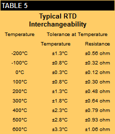
RTDs, for example, contain a sensing element that is manufactured to have a specific electrical resistance at a specific temperature. The most common example of this requirement is the DIN (Deutsches Institut für Normung) standard. To meet the requirements of the DIN standard, an RTD must have a resistance of 100 Ω±0.12% (or 0.12 Ω) at 32°F (0°C) to be considered a Grade B sensor (a Grade A sensor is 100 Ω±0.06%). The tolerance of ±0.12 Ω applies only to the resistance at 32°F and not to any other temperature. Many suppliers will provide an interchangeability table for RTDs that lists tolerances at specific temperatures (see Table 5).
Most IC sensors provide an output value that is proportional with temperature over a specific temperature range. These devices are usually supplied with a standard accuracy assigned, but also include the ability to be calibrated at a specific temperature.
Thermistors, like RTDs, have a specified resistance value with a plus-or-minus tolerance at a particular temperature. This temperature point will vary somewhat according to the application. Unlike RTDs, with resistance usually specified at 0°C, thermistors are typically specified at 25°C.
Thermistors differ from RTDs also in that there are no standard resistance vs. temperature characteristics. Suppliers provide their own resistance table for each type of material they produce, normally published as ratios based on the device's resistance at 25°C so that they can be used for a variety of resistance values.
Thermocouples are specified differently because they are manufactured differently. In contrast to the sensing element in RTDs or thermistors, the millivolt potential generated in a thermocouple is a function of the material composition and the metallurgical structure of the conductors. Thermocouples therefore are not assigned a value at a specific temperature, but instead given limits of error that cover an entire temperature range.
These limits assigned to thermocouples are known as standard or special limits of error. Table 3 lists the standard and special limits of error specifications for each standard thermocouple type. It should be noted that these limits pertain to new thermocouples prior to use. Once the devices are exposed to process conditions, changes in the conductors may result in increased errors. Users are encouraged to perform tests periodically to determine the condition of thermocouples in high-reliability or close-accuracy applications.
Strengths and Weaknesses
RTD Strengths. RTDs are commonly used in applications where repeatability and accuracy are important. Properly constructed platinum RTDs have very repeatable resistance vs. temperature characteristics over time. If a process will be run at a specific temperature, the specific resistance of the RTD at that temperature can be determined in the laboratory, and it should not vary significantly over time. RTDs also allow for easier interchangeability since their original variation is much lower than that of thermocouples. For example, a Type K thermocouple used at 400°F has a standard limit of error of ±4°F. A 100 Ω DIN, Grade B platinum RTD has an interchangeability of ±2.2°F at this same temperature. RTDs can be used with a standard instrumentation cable for connection to display or control equipment; thermocouples must have matching thermocouple wire to obtain an accurate measurement.
RTD Weaknesses. For a given configuration, an RTD can be expected to cost 4 to 10 times more than a base metal thermocouple. The reason for the difference is that more work goes into making RTDs, including manufacture of the sensing element, hooking up extension wires, and assembly of the sensor. Because of the construction of the sensing element, RTDs do not do so well as thermocouples in high-vibration and severe mechanical shock environments. Their maximum temperature is limited to ~1200°F; thermocouples can withstand 3100°F.
IC Sensor Strengths. Within their effective temperature range, IC sensors provide good linearity at low cost. They offer output values that are proportional with temperataure, and do not require the additional signal conditioning necessary for RTDs, thermocouples, and thermistors. Many IC sensors also offer communication protocols for use with bus-type data acquisition systems; some also have addressability and data storage and retrieval capabilities.
IC Sensor Weaknesses. The major drawback of IC sensors is their limited temperature range, generally -55°C to 150°C. These sensors are typically larger than RTDs and thermistors, and they require larger package sizes for immersion-type measurements.
Thermistor Strengths. The resistance vs. temperature change of thermistors is significantly larger than that of RTDs, so thermistors provide more resolution over a given range. Thermistors' higher resistance values allow them to be used with longer lead wires without requiring lead wire compensation. Their small size and mass means that they can be packaged in a wide variety of assemblies, and may react faster to changes in temperature than do RTDs. They are also generally less expensive than RTDs.
Thermistor Weaknesses. The resistance vs. temperature characteristics for thermistors are highly nonlinear; these sensors are therefore used in applications with limited temperature ranges. Thermistors are also limited to much lower temperature exposures than either RTDs or thermocouples. The lack of industry standards presents a problem when replacing thermistor sensors. OEMs choosing to purchase replacement sensors from a supplier other than the original source may have to contend with differences in sensor output, depending how closely another supplier can match the original characteristics.
Thermocouple Strengths. Thermocouples can be used to measure temperatures as high as 3100°F, generally cost less than RTDs, and can be made smaller in size (down to ~0.020 in. dia.) to permit faster response to temperature. Thermocouples are also more durable than RTDs, and can therefore be used in high-vibration and high-shock applications.
Thermocouple Weaknesses. Thermocouples are less stable than RTDs when exposed to moderate- or high-temperature conditions. In critical applications, thermocouples should be removed and tested under controlled conditions in order to verify performance. Thermocouple extension wire must be used in hooking up thermocouple sensors to thermocouple instrument or control equipment. Use of instrumentation wire (plated copper) will result in errors when ambient temperatures change.
Summary
RTDs, thermocouples, thermistors, and IC sensors are all useful temperature measurement options, with thermistors and IC sensors relegated to narrower temperature ranges than RTDs and thermocouples.
RTDs provide higher accuracy because platinum is more stable than most of the materials used in thermistors, thermocouples, and IC sensors. RTDs, thermistors, and IC sensors use standard instrumentation wire to connect to the measurement or control equipment. Thermocouples, on the other hand, require special thermocouple extension wire.
Within their limited temperature range, IC sensors provide the advantage of linear temperature output and low cost. They can also have bus-type addressability and data storage and retrieval.
Thermistors provide higher resolution than RTDs or thermocouples, and generally cost less. Their lower temperature range and nonlinearity limit their ability to function over large temperature excursions. Their low mass and small size give them quick response to temperature changes. The lack of standard resistance vs. temperature curves can cause difficulty in replacing sensors when needed.
Thermocouples are generally less expensive than RTDs, but are competitive with thermistors and IC sensors in some applications. They are more durable in high-vibration or mechanical shock applications, and are usable for measuring high temperatures. Because the different types of thermocouples are standardized, they can be easily replaced when necessary. At present, thermocouples are the major players in the temperature sensing field, but are losing ground to RTDs, thermistors, and IC sensors.
About the authors
Ron Desmarais is Design and Development Engineering Manager and Jim Breuer is Market Research and Communications Engineer, Airpax, Thermal Sensing Division, 550 Highland St., PO Box 500, Frederick, MD 21701; 301-663-5141, fax 301-698-0624, [email protected], ron.desmaris@air pax.net.