
Traditional industrial encoders, whether incremental or absolute, can meet the needs of many general industrial motion control applications. However, these devices are more likely to fail when placed in operating environments that subject them to aggressive contaminants, impact, high shock and vibration, long-term submersion in liquids, intensive cleaning procedures, or EMI noise.
Many industrial manufacturers like to use standard off-the-shelf encoders without realizing the total impact of the operating environment on the machine. When standard encoders fail, downtime costs related to encoder failure can quickly grow to several times the cost of the encoder itself. This article concentrates on heavy-duty encoders: the engineering principals behind their operation and how the technology used ensures their long-term survival under extremely challenging conditions. Real-world examples will illustrate their use and benefits.
Traditional Encoders and How They Work
There are six main components of every optical encoder (Figure 1):
- shaft and bearing assembly,
- pulse disc,
- light source,
- grid diaphragm,
- photodiode/decoding circuitry, and
- connector.
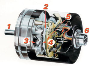 Figure 1. A diagram of an optical encoder |
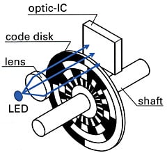 Figure 2. Operation of a quadrature encoder |
All optical encoders operate in the same basic way (Figure 2). The light source directs rays through a plane convex lens that focuses the light into a parallel beam. The light beam passes through the grid diaphragm, which splits it to produce a second beam of light 90° out of phase. Light passes from the original (A) and the second (B) channel through a tempered glass, polycarbonate, or metal pulse disc onto the photovoltaic or photodiode array. The pulse disc turns, creating a light/dark pattern through the clear and opaque segments of the disc.
The light/dark pattern is read and processed by the photodiode array and decoding circuitry. Light beams A and B are each received by a separate diode and converted into two square wave signals, 90° out of phase, commonly known as a quadrature output. The quadrature output is then fed into a controlling device that can process the signal to determine the number of pulses, direction, speed, and other information.
To operate flawlessly, optical encoders require a clean path from their emitter diodes to their receiver array through the pulse disk, which is located directly between the two. The encoder shaft—and therefore the connected pulse disk—rotates, forming a critical interface between the encoder electronics, the shaft, and the bearing assembly.
It is not possible to manufacture a 100%-sealed optical encoder because the bearing-to-shaft assembly will never be perfectly tight. There must be a clearance to allow the bearing to slide over the shaft during assembly of the encoder. This clearance creates openings or paths through which contaminants can enter.
Bearings allow the shaft to turn while permitting the housing to remain still. Because they are not designed to support high loads under normal circumstances, mechanical bearings can become overloaded in harsh environments. Common causes of bearing failure are shock, vibration, and excessive radial and axial loads. Even bearings with rubber or plastic lip seals and with high IP ratings cannot cover all rotational speeds, encoder designs, and mounting positions; all seals are subject to wear, aging, and the effects of UV radiation.
On a factory floor, standard industrial encoders can deliver erratic signal output resulting from damage to the sensitive ICs that transmit quadrature output to the controlling device. Such damage can be caused by EMI or radiated noise from factory equipment surrounding the encoder. In large factories, long distances between the encoder and the controlling electronics can impair the quadature output, resulting in intermittent failures.
Challenges Posed by Harsh Environments
Encoders are commonly used in a range of harsh or challenging end-use applications including food/beverage processing, heavy equipment, cranes, specialty vehicles, energy generation equipment, chemical/petroleum processing, medical devices, wastewater treatment, shipbuilding and marine vehicles, printing equipment, and other indoor and outdoor uses.
In such harsh environments, there are three common causes of encoder failure: 1) solid particulate or liquid contamination, 2) mechanical bearing overload, and 3) signal output failure. As a result of any of these problems, the encoder will cease to operate or the system will operate erratically.
Ambient temperature variations can accelerate encoder failure rates. During encoder cool down, pressure differences between the outside environment and the inside of the housing can cause the encoder to "breathe," drawing air into the housing. As the temperature of an encoder's housing drops, any contained humidity will condense inside the housing, resulting in dew collecting on PCBs, wiring, and the code disk, which can lead to encoder failure.
In many applications, liquid ingress naturally occurs when encoders come into direct external contact with water, coolants, lubricants, and cleaning agents. Often, these applications are found outdoors or in environments—such as food and beverage processing facilities—subject to high-pressure wash down. For example, when yogurt is placed into containers during production, an encoder is often used to monitor the rotation of the rotary table that controls container filling. At the end of a day's production run, the packaging machine is washed down for sanitation purposes, a process that involves cleaning the equipment by spraying high-pressure hot liquid onto the machinery.
Encoders in harsh environments are often exposed to particulates such as sand, salt, small wood chips, or dust particles. These particulates will enter the encoder, blocking optical processes, and resulting in the failure of the device. In paper processing, encoders monitor the speed or position of the rotary processes that control the flow of pulp into the machine and the feed of paper onto spools. Paper production is a notoriously dirty process, and the environment is filled with small liquid drops containing pulp. In its liquid form, pulp collects on nearly everything in the plant, resulting in the formation of a fur on all components, including the encoders. Even standard industrial encoders with high IP ratings will not withstand such contamination for long. Encoder failure quickly occurs as particulates enter the encoder housings and block the internal optical equipment.
Heavy-Duty Encoders
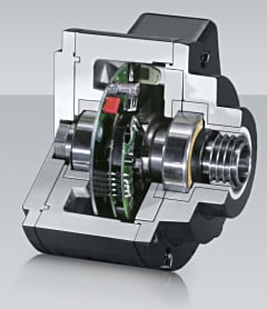 Figure 3. A heavy-duty encoder with robust housing |
To withstand liquid and solid particulate contamination, heavy-duty encoders feature solid die-cast housings and robust designs that permit their reliable operation in open-air applications where normal encoders would fail (Figure 3). As their first line of defense, heavy-duty encoders incorporate labyrinth seals that have reverse-lead spiral grooves to prevent the ingress of liquids and particulates into the housing. These seals allow the devices to be exposed to moisture, temperature extremes, salt spray, chemicals, and vibration above the limits of traditional encoders.
The encoders also feature larger ball bearings fitted on opposite sides of the solid die-cast housing that surrounds the sensor electronics. Although these encoders typically take up more space, their shafts are preloaded to withstand much greater forces in both radial and axial directions. This robust construction allows harsh-duty encoders to survive shocks up to 500 g and to operate reliably in temperatures from –40°C to 100°C.
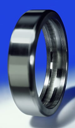 Figure 4. Raceway damage—caused when shaft currents damage the ball bearings—shows as a corrugated surface in the ball race. |
Patented ceramic ball bearings with special isolation resistance between the housing and shaft of the encoder prevent the buildup of shaft currents from large AC motors and generators. These shaft currents have the potential to flow through the earthed encoder housing to the ground and are very dangerous because spark erosion can cause lasting damage to the bearings and the bearing surfaces (Figure 4).
In all rotary encoders, the sensor electronics and code disk are located inside the housing between the bearings. In heavy-duty encoders, code disks are made of metal rather than glass or plastic. Glass disks are susceptible to scratching and fracture under shock. Plastic disks are quite shock resistant but are more likely to warp and lose their shape at higher temperatures; they are also more likely to break down in chemically aggressive environments. Metal disks better withstand shock, heat, and chemicals and will not break down in harsh-duty applications.
The die-cast housing found on heavy-duty encoders allows the length of the shaft to be extended between bearings to allow a second encoder device or a mechanical centrifugal switch to be mounted. The second device triggers an action when a specific speed limit is exceeded. It is electronically independent of the first system, providing redundancy in applications where extreme safety is required (Figure 5). For example, if the blades on a wind turbine are turning too fast in a windstorm, the secondary device slows the blades to protect the turbine from damage.
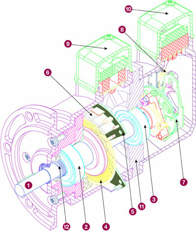 Figure 5. A diagram of an encoder for a wind turbine showing (1) the heavy-duty shaft assembly, (2 and 3) insulated ceramic bearings, (4) a metal code disk, (5) a heavy-duty electronics board, (6) 300 mA power transistors, (7 and 8) redundant speed switches, (9 and 10) separated terminal boxes, (11) separator plate, and (12) special labyrinth seals |
To prevent signal output failure, specially coated large terminal boxes can provide resistance to electromagnetic fields.
Encoder Testing
Heavy-duty encoders must be continually tested to verify that they can withstand difficult environments. During development, the assembled printed circuits are tested and optimized for the resonant frequencies of the components (Figure 6) using a measurement rig with continuously tunable frequency and amplitude (a sine-wave sweep from 10–2000 Hz). This ensures that components do not vibrate excessively (to the detriment of the output circuit) or break loose. Electromagnetic compatibility (EMC) is tested by measuring the burst voltage (Figure 7).
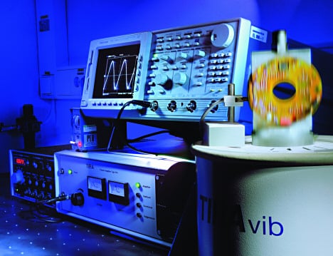 Figure 6. Resonant frequency testing |
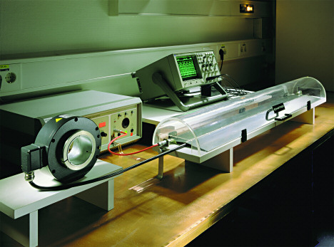 Figure 7. EMC testing |
The encoders then go through vibration, continuous shock, dust protection, and water jet testing. The water jet test subjects the encoder to a strong jet of water at a pressure of 12 bars and a flow rate of 100 lpm. The encoder is also immersed in water to a depth of 1 m to test that its sealing complies with IP67 standards. Some encoders are exposed to a sprayed salt mist test for marine applications and a humid heat test to verify their tropical suitability. These tests usually ensure that the corrosive failures that happen to standard encoders in harsh environments will not occur on heavy-duty encoders operating in the same environments (Figure 8).
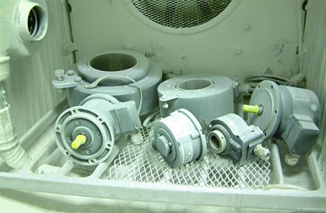 Figure 8. Encoders are sprayed with a salt mist to test their ability to survive in marine applications |
For marine and specialized food-grade and wash-down environments, heavy-duty encoders with full stainless steel housings use a specialized Simmerring seal for deep immersion (Figure 9) and a hermetic encapsulation process to protect the electronics of the encoder from the outside world. The only thing that can pass through the encapsulation is the magnetic field of the permanent magnet on the encoder. These encoders reach the highest protection classes of IP68 and IP69K and can be submerged in liquids for long time periods or cleaned with pressure washers without failing.
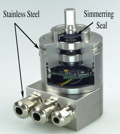 Figure 9. A heavy-duty encoder with a Simmerring seal and heavy SS construction |
One of the toughest real-world applications for heavy-duty encoders involves their use on the latest generation of fire extinguisher boats. In this application, heavy-duty encoders manage the positioning of remote-controlled jet pipes that throw tons of seawater per minute over a distance of more than 100 m directly onto a fire. To effectively control the jet pipes, the encoders are positioned with the shaft side facing upward. This positioning would allow seawater to rapidly enter a standard industrial encoder. Because of the encoders' hermetic sealing, seawater cannot enter the encoder housing, preventing associated damage to internal electronics.
A number of end-use applications require encoders with features specifically suited for the demands of harsh environments. Standard encoders often lack the durability to last in these environments. In contrast, heavy-duty encoders, with their protective housings, robust design, and large ball bearings, work in applications where standard encoders cannot.