
To begin our investigation of pressure sensors, we first must consider the physics on which the technology is based.
Static Pressure. Pressure, P, is defined as force, F, per unit area, A:
| P = F/A | (1) |
The measurement of pressure is generally associated with fluids, either
liquids or gases. A container filled with a liquid (see Figure 1) has a
|
P = |
(2) |
where:
| h | = distance from the surface to the point |
| w | = weight of the liquid (most liquids are nearly incompressible) |
 |
The weight per unit volume, V, is given by:
| w = mg/V | (3) |
where:
| m | = mass |
| g | = gravitational acceleration |
Note that this relation can be used to determine the height of the column of liquid in a tank by measuring the pressure.
The density, ![]() , is given by:
, is given by:
|
|
(4) |
Thus, the density of a liquid determines the pressure, P, exerted for a given height. Mercury is 13.6 3 denser than water, so would exert a pressure 13.6 3 that of water for a column of the same height. It should be noted that the pressure due to the height of a column of liquid is in addition to the atmospheric pressure acting on the surface of the liquid. The height
of a column of liquid is:
|
h = P/ |
(5) |
Archimedes's principle states that "A body wholly or partially submerged in a liquid is buoyed up by a force equal to the weight of the liquid displaced." Given a block of material submerged in a container of liquid (see Figure 2) with area A and length L, the downward pressure exerted on the top face is:
|
PD = h |
(6) |
 |
and the upward pressure exerted on the bottom face is:
|
PU = (h + L) |
(7) |
giving a resultant pressure of:
|
PU - PD = L |
(8) |
and the force is equal to the volume of the block multiplied by the weight of the liquid displaced.
 |
A liquid exhibits nearly no shear stress, which leads to some interesting results. Pressure is transmitted to the inside of a container normal to the surfaces, a fact that can be most easily proved by punching a hole in a container of water and observing the stream as it exits the hole (see Figure 3). This is important in the construction of dams, given that they must resist the force of water. This pressure is called the static pressure.
Pascal's law states that an increase in pressure at any point in a liquid results in a like increase at every other point in the liquid. This principle is used in hydraulic systems such as jacks and automobile brakes and is the fluidic equivalent of the principle of the lever, which allows large forces to be generated easily by trading large movement of a small piston for small movement of a large piston (see Figure 4).
 |
Pressure in Moving Fluids. The pressure in a moving fluid exerted parallel to the flow direction is called the impact pressure, PI. This is due to the kinetic energy of the fluid:
|
PI = |
(9) |
where:
| = fluid density |
|
| VO | = fluid velocity |
Bernoulli's theorem states that for horizontal flow the following relation holds:
| PS = PO + PI | (10) |
where:
| PS | = stagnation (or total) pressure |
| PO | = static pressure |
This relationship is useful for determining the flow velocity in a variety of applications. Rearranging the equation gives:
|
|
(11) |
 |
Gases. Gases differ from liquids in two respects: they are very compressible, and they completely fill any closed vessel in which they are
 |
Dynamic Effects. Static pressure is measured under steady-state or equilibrium conditions, but most real-life applications deal with dynamic or changing pressure. For example, the measurement of blood pressure usually gives the two steady-state values of systolic and diastolic pressure. There is much additional information in the shape of the blood pressure signal, however, which is the reason for the monitors used in critical-care situations.
To measure changing pressures, the frequency response of the sensor must be considered. As a rough approximation, the sensor frequency response should be 5-10 × the highest frequency component in the pressure signal. The frequency response is defined as the highest frequency that the sensor will measure without distortion or attenuation. Sometimes the response time is given instead. For a first-order system, they are related as follows:
|
FB = 1/2 |
(12) |
where:
| FB | = frequency where the response is reduced by 50% |
| = time constant where the output rises to 63% of its final value following a step input change |
Another issue is the remote measurement of pressure where a liquid coupling medium is used. Care must be taken to purge all air because its compressibility will corrupt the waveform.
Types of Pressure MeasurementsAbsolute pressure is measured relative to a perfect vacuum. An example is atmospheric pressure. A common unit of measure is pounds per square inch absolute (psia).
Differential pressure is the difference in pressure between two points of measurement. This is commonly measured in units of pounds per square inch differential (psid).
Gauge pressure is measured relative to ambient pressure. Blood pressure is one example. Common measurement units are pressure per square inch gauge (psig). Intake manifold vacuum in an automobile engine is an example of a vacuum gauge measurement (vacuum is negative gauge pressure).
 |
As previously noted, pressure is force per unit area and historically a great variety of units have been used, depending on their suitability for the application. For example, blood pressure is usually measured in mmHg because mercury manometers were used originally. Atmospheric pressure is usually expressed in in.Hg for the same reason. Other units used for atmospheric pressure are bar and atm. The following conversion factors should help in dealing with the various units:
| 1 psi | = 51.714 mmHg |
| = 2.0359 in.Hg |
|
| = 27.680 in.H2O |
|
| = 6.8946 kPa |
|
| 1 bar | = 14.504 psi |
| 1 atm. | = 14.696 psi |
Example: Convert 200 mmHg to psi:
200 mmHg 1 psi/51.714 mmHg = 3.867 psi
 |
Pressure is sensed by mechanical elements such as plates, shells, and tubes that are designed and constructed to deflect when pressure is applied. This is the basic mechanism converting pressure to physical movement. Next, this movement must be transduced to obtain an electrical or other output.
 |
Sensing Elements
The main types of sensing elements are Bourdon tubes, diaphragms, capsules,
and bellows (see Figure 9). The Bourdon tube is a sealed tube that
deflects in response to applied pressure. All except diaphragms provide
a fairly large displacement that is useful in mechanical gauges and for
electrical sensors that require a significant movement.
Mechanical Pressure Gauges. In mechanical gauges, the motion created by the sensing element is read directly by a dial or pointer. These devices are typically seen in low-performance applications, including blood pressure measurement and automotive pressure gauges. The mechanical approach used to couple the sensing element to the readout can introduce repeatability
 |
Electromechanical
Pressure Sensors. Electromechanical pressure
sensors convert the applied pressure to an electrical signal. A wide variety
of materials and technologies has been used in these devices, resulting
in performance vs. cost tradeoffs and suitability for applications. The
electrical output signal also provides a variety of choices for various
applications.
Sensor Effects. A pressure sensor may be modeled as:
| VOUT = kO + k1P | (13) |
where:
| kO | = offset |
| k1 | = pressure sensitivity in V/pressure unit |
 |
Linearity refers to deviations from the ideal straight line described by Equation (13). One way to measure linearity is to use the least squares method, which gives a best fit straight line (see Figure 12).
 |
Hysteresis refers to the ability of the sensor to give the same output when the same increasing and then decreasing pressures are applied consecutively (see Figure 14).
Temperature hysteresis refers to the ability of the sensor to give the same output at a given temperature before and after a temperature cycle. Repeatability and hysteresis effects are not easily compensated and
 |
Gauge factor is a measure of the sensitivity of a sensor. It is defined as the ratio of the change in an electrical transduction parameter over the full range of pressure to the value of that parameter at zero pressure.
Thus, the gauge factor of a resistive sensor is:
|
|
(14) |
where:
| R | = base resistance |
| = resistance change with full-scale pressure, for example |
 |
Pressure Sensor Technologies
Potentiometric Pressure Sensors. Potentiometric pressure sensors
 |
Inductive Pressure Sensors. Several configurations based on varying inductance or inductive coupling are used in pressure sensors. They all require AC excitation of the coil(s) and, if a DC output is desired, subsequent demodulation and filtering. The linear variable differential transformer
 |
Capacitive Pressure Sensors. Capacitive pressure sensors typically use a thin diaphragm as one plate of a capacitor. Applied pressure causes the diaphragm to deflect and the capacitance to change. This change may or may not be linear and is typically on the order of several picofarads out of a total capacitance of 50-100 pF. The change in capacitance may be used to control the frequency of an oscillator or to vary the coupling of an AC signal through a network. The electronics for signal conditioning should be located close to the sensing element to prevent errors due to stray capacitance.
The capacitance of two parallel plates is given by:
| C = µA/d | (15) |
where:
| µ | = dielectric constant of the material between the plates |
| A | = area of the plates |
| d | = spacing between the plates |
 |
Piezoelectric Pressure Sensors. Piezoelectric elements are bi-directional transducers capable of converting stress into an electric potential and vice versa. They consist of metallized quartz or ceramic materials. One important factor to remember is that this is a dynamic effect, providing an output only when the input is changing. This means that these sensors can be used only for varying pressures. The piezoelectric element has a
 |
Strain Gauge Pressure Sensors. Strain gauge sensors originally used a metal diaphragm with strain gauges bonded to it. A strain gauge measures the strain in a material subjected to applied stress. Consider a strip of metallic material (see Figure 20) with electrical resistance given by:
|
RO = |
(16) |
where:
| = resistivity |
|
| L, W, T | = length, width, thickness |
|
|
Metallic strain gauges depend only on dimensional changes to produce a change in resistance. A stress applied to the strip causes it to become slightly longer, narrower, and thinner, resulting in a resistance of:
|
R = R |
(17) |
As might be expected, the signal due to deformation of the material is small, on the order of 0.1% of the base resistance.
 |
 |
Bonded semiconductor strain gauge. A silicon bar may be bonded to a diaphragm to form a sensor with relatively high output. Making the diaphragm from a chemically inert material allows this sensor to interface with a wide variety of media (see Figure 21).
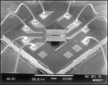
Piezoresistive Integrated Semiconductor. IC processing is used to form the piezoresistors on the surface of a silicon wafer (see Photo 1). There are four piezoresistors within the diaphragm area on the sensor. Two are subjected to tangential stress and two to radial stress when the diaphragm is deflected.
 |
They are connected in a four-element bridge configuration (see Figure 22) and provide the following output:
|
VOUT/VCC = |
(18) |
where:
| VCC | = supply voltage |
| R | = base resistance of the piezoresistor |
| = change with applied pressure and is typically ~2.5% of the full R |
 |
 |
 |
Because the sensing element is so small (see Photo 2), the package can have a great deal of mounting and port interface flexibility. Also, the small size means that it has a wide frequency response and may be used for dynamic pressure measurements without concern about errors. Mechanical vibration and acceleration have a negligible effect.
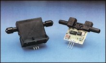
Using a Flow Sensor to Measure Pressure. A recently developed
 |
Because of its small size and excellent thermal resistance, only a few milliwatts of power are required to achieve high air flow sensitivity. By calibrating the device with a flow restriction for a specified pressure drop, a sensor capable of measuring pressures of a few inches of water results. This is ideal for airflow measurement in HVAC applications, for example.
The sensor operates on the principle of heat transfer due to mass airflow directed across the surface of the sensing element (see Figure 25).
 |
Output voltage varies in proportion to the mass air (or other gas flow) through the inlet and outlet ports of the package (see Photo 4). The sensor
 |
Pressure Switches. Pressure switches, combining a diaphragm or other pressure measuring means with a precision snap switch, can provide precise single-point pressure sensing. Alternatively, simple electronic switches may be combined with electrical sensors to construct a pressure switch with an adjustable set point and hysteresis.
Electrical Interfacing. Care must be taken with the output from a pressure sensor to avoid corrupting the signal by noise or 60 Hz AC pickup. If the signal must be run some distance to the interface circuitry, twisted and/or shielded wire should be considered. A decoupling capacitor located at the sensor and connected from the supply to ground will also filter noise, as will a capacitor from output to ground.
For long runs, a current output sensor should be considered. These devices have a 2-wire interface and modulate the supply current in response to applied pressure. Obviously, wire resistance has no effect and noise must change the loop current, not simply impress a voltage on the signal. The industry standard interface is:
| PL = 4 mA | (19) |
| PH = 20 mA | (20) |
where:
| PL | = low pressure range limit |
| PH | = high pressure range limit |
 |
With this approach, runs of 1000 ft or more are possible.
Manufacturers of pressure sensors have elaborate calibration facilities to verify the accuracy of their production test equipment. These include dead weight testers and temperature-controlled servo-rebalance testers using Bourdon tubes made from high-stability quartz.Dead-Weight Tester. A dead-weight tester uses calibrated weights that exert force on a piston which then acts on a fluid to produce a test pressure. For high pressures (>500 psi), oil is typically used (see Figure 26); for lower pressures, pneumatic air bearing testers are available and are much more convenient as well as less messy to use.
Manometer. A mercury manometer is a simple pressure standard and may be used for gauge, differential, and absolute measurements with a suitable reference. It is useful mainly for lower pressure work because the height
 |
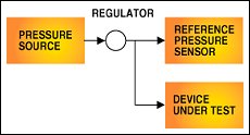
Low-Cost Calibration. Many of the higher performance commercially available pressure sensors are furnished with individual test data. A sensor with excellent repeatability and hysteresis makes an excellent low-cost in-house pressure calibration reference when combined with a pneumatic pressure regulator and a source of air pressure (see Figure 28).
Selection ConsiderationsSelection of a pressure sensor involves consideration of the medium for compatibility with the materials used in the sensor, the type (gauge, absolute, differential) of measurement, the range, the type of electrical output, and the accuracy required. Manufacturer's specifications usually apply to
 |
Given the following error terms:
- Linearity = 1% F.S.
- Null calibration = 1% F.S.
- Sensitivity calibration = 1% F.S. Temperature errors are sometimes given as coefficients per ºC referenced to 25ºC. Simply multiply the coefficient by the temperature range of the application to obtain the total error.
- Temperature error = 0.5% F.S.
- Repeatability and hysteresis = 0.1% F.S.
|
|
(21) |
Worst case error is equal to the sum of all the maximum errors:
| Worst case error = 1 + 1 + 1 + 0.5 + 0.1 = 3.6% | (22) |
Applications
Industrial. Fluid level in a tank: A gauge pressure sensor
located to measure the pressure at the bottom of a tank can be used for
a remote indication of fluid level using the relation:
|
h = P/ |
(23) |
Fluid flow: An orifice plate placed in a pipe section creates a pressure drop. This approach is widely used to measure flow because the pressure drop may be kept small in comparison to some other types of flowmeters and because it is impervious to clogging, which may otherwise be a problem when measuring flow of a viscous medium or one containing particulate matter. The relation is:
|
|
(24) |
In some cases, differential pressures of only a few inches of water are measured in the presence of common-mode pressures of thousands of pounds per square inch. These pressure sensors are built with elaborate mechanisms to prevent damage due to the high common-mode pressures and also frequently have remotely controllable pressure ranging.
Automotive. A wide variety of pressure applications exist in the modern electronically controlled auto. Among the most important are:
Manifold absolute pressure (MAP). Many engine control systems use the speed-density approach to intake air mass flow rate measurement. The mass flow rate must be known so that the optimum amount of fuel can be injected. MAP is used in conjunction with intake air temperature to compute the air density. This requires a 15 psia range or higher (for supercharged or turbocharged engines). It is also desirable to include an altitude correction in the control system, and this requires measurement of barometric absolute pressure (BAP). Some systems use a separate sensor, but it is more common for the MAP sensor to do double duty since it reads atmospheric pressure for two conditions. One, before the engine begins cranking and two, whenever the throttle is wide open.
Engine oil pressure. Engine lubrication requires pressures of 10-15 psig. The oil pump is sized to achieve this pressure at idle and the pressure increases with engine speed. A potentiometric gauge or pressure switch is used for this function since precision isn't required.
Evaporative purge system leak detection. To reduce emissions, modern fuel systems are not vented to the atmosphere. This means that fumes resulting from temperature-induced pressure changes in the fuel tank are captured in a carbon canister and later recycled through the engine. Government regulations require that leaks in this system be detected by the onboard diagnostics system. One approach is to pressurize the system and measure pressure decay over a fixed time interval. A 1 psig sensor is used for this function.
Tire pressure. Recent development of the "run-flat" tire has prompted development of a remote tire pressure measurement system. The reason is that a flat tire of this type is difficult to detect visually and the distance over which it can be used without any pressure is limited.