
In almost all new vehicles, an electronic engine control module teams with sensors and actuators to constitute the engine control system. One of this system's most critical inputs is manifold absolute pressure (MAP). In the "speed density" regime, the MAP permits inference of the mass air flowing in the engine and enables determination of the fuel and spark advance for optimum operation. Even vehicles that rely on direct mass airflow measurement contain a companion barometric absolute pressure (BAP) sensor, primarily for altitude compensation. Tens of millions of MAP and BAP sensors are produced annually, and their prevalence over the past decade has fueled several generations of sensor module design.
Today, the dominant design for MAP/BAP sensors is the micromachined silicon piezoresistive pressure sensor. Found in most passenger vehicles, these MAP/BAP sensors have set the stage for micromachined pressure sensor technology to be used in other emerging automotive applications, such as measurement of pressure in exhaust gas recirculation systems (EGR), leaks in fuel systems for evaporative emissions, and fuel injection system pressure.
The Pressure Sensor Element
Piezoresistive transducers implanted in a silicon wafer with bulk micromachined diaphragms have become the dominant technology for producing automotive pressure sensors. Initially an absolute, bulk micromachined, piezoresistive pressure sensor element with a backside constraint for the formation of a vacuum reference cavity--a necessary element for MAP/BAP applications--emerged as the most popular configuration. Lately, however, gauge and differential configurations, as well as configurations where a backside constraint is added for a stress relief only (see Figure 1), have evolved to significant production volumes.
 Figure 1. To meet the wide range of applications required by the automotive market, sensor manufacturers must be capable of providing multiple sensor element configurations for measuring low to high pressure ranges in absolute, gauge, or differential format. |
Signal Conditioning and Calibration
Silicon micromachined pressure sensor elements exhibit wide variation of their parameters from part to part, as well as over temperature (see Figure 2). To produce a truly interchangeable module for vehicle manufacturers, sensor developers must individually calibrate and temperature-compensate each sensor.
 Figure 2. Batch processed micromachined silicon piezoresistive sensor elements exhibit part-to-part variation across a wafer, from wafer to wafer, and from lot to lot. Individual piezoresistive elements also vary significantly over temperature. Consequently, individual trimming and calibration of each packaged sensor are required during final assembly of the sensor module. |
The usual method is to use some sort of adjustment (trimming) within the signal conditioning circuit. The manufacturing and assembly methods and the finished sensor module's electrical performance requirements help determine how the signal conditioning circuit is implemented. Integration technology for this circuit--CMOS, BiCMOS, or bipolar--depends primarily on the selected trimming technique.
Analog Signal Conditioning. At first, automotive piezoresistive pressure sensors contained analog signal conditioning circuits, built using off-the-shelf, packaged, bipolar ICs that were mounted on a PCB. All the necessary adjustments were done using laser trimming of the thick film resistor network that was deposited on a ceramic substrate and then inserted into the PC board in the form of a trim-pack. Subsequent advances in hybrid circuit technology permitted both fabrication of the ceramic substrate containing printed thick film resistors, and mounting of the signal conditioning ICs in either packaged or bare-die form. These sensor modules became fairly compact, and significant volumes of them are still in production. This mature manufacturing process provides cost-effective sensor modules for applications with moderate size requirements, where thick film resistor stability and accuracy are adequate.
The automotive industry's constant drive for low-cost components, however, forced higher levels of integration to minimize the component count and assembly cost of pressure sensor modules. As a result, analog active circuits were integrated on the same chip with passive, thin film trimmable resistors. By doing this, manufacturers dramatically reduced sensor module sizes and improved sensor performance, primarily because of the thin film resistor's superior stability. Integration of that type has created two-chip solutions, with the sensing element as one chip and the IC with thin film resistors as the other. Monolithic (single-chip) solutions, in which the sensing element, active circuit, and thin film resistors are integrated on one silicon die, are also used in volume production.
All of the above signal conditioning circuits are analog in nature, and the laser trimming adjustments are assumed to be continuous.
Discrete-Analog Trimming. The second flavor of signal conditioning of piezoresistive pressure sensors, discrete-analog trimming, is based on discrete rather than continuous adjustments. In this case, fusible links can be opened to make steps in the resistance or current value. The processing of the sensor signal remains in analog form, but calibration and trimming are done using discrete steps; this may limit the sensor's accuracy, resolution, and range of authority. The discrete analog signal conditioning approach can be expanded even further, because the adjustment levels can be stored in nonvolatile memory and implemented in CMOS technology. Piezoresistive pressure sensors manufactured with the discrete analog approach have been built with two chips using mixed technologies. One chip, which stores the calibration coefficients in EPROM, is implemented in CMOS technology; the second chip includes the sensing element and amplifiers and is implemented in bipolar technology.
The Digital Option. Piezoresistive pressure sensors' signals can also be conditioned using digital signal processing (DSP). In this method, pressure and temperature signals are digitized and then presented as inputs to a DSP algorithm. Calibration and temperature compensation are implemented using an arithmetic operation, after which the digital signal is converted back to the analog domain.
Digital solutions require some memory, and thus lend themselves best to CMOS technology. This approach has been considered for many years; implementation required multiple chips, however, and the associated higher costs of such a solution have not been suitable for automotive implementation. As CMOS process and microcontroller/DSP technology become more advanced and highly integrated, this approach may become increasingly popular. Debate continues as to whether the chip area and circuit overhead of standard microprocessor designs used for this purpose will be competitive with less flexible (but smaller and less costly) dedicated DSP designs that can be customized to perform the specific sensor calibration function.
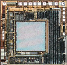 Photo 1. This monolithic pressure sensor uses a custom digital signal processing circuit and nonvolatile memory to calibrate and temperature-compensate on-chip piezoresistive pressure and temperature sensing elements. The digital signal conditioning approach also provides for programming of unique customer-specific features. |
This programmable signal conditioning engine operates in the digital domain using a calibration algorithm that accounts for higher order effects beyond the realm of most analog signal conditioning approaches. The monolithic sensor provides enhanced features that typically were implemented off the chip (or not at all) with traditional analog signal conditioning solutions that use either laser or electronic trimming. A specially developed digital communication interface permits calibration of the individual sensor module via connector pins after the module has been fully assembled and encapsulated. Post-trim processing is eliminated, and calibration and module customization can be performed as an integral part of end-of-line testing at the completion of the manufacturing flow. The IC contains a pressure sensor element that is coprocessed in a submicron, mixed-signal CMOS wafer fabrication step and that can be scaled to a variety of automotive pressure sensing applications. Both digital and analog sensor outputs are available.
Manufacturing and Assembly Considerations
The module assembly process plays a large part in a manufacturer's decision as to which trimming and calibration method to use, and thus affects the electrical circuit design as well. Laser trimming methods require optical access to the module at some intermediate point in the assembly process to perform calibration. This step typically involves the application of temperature and pressure, which makes for complicated production fixturing that requires careful maintenance and calibration. As all current high-volume automotive pressure sensor designs require some type of calibration to ensure interchangeability at the customer level, trimming becomes a critical step that has significant impact on manufacturing cost and production rates. This is particularly true for monolithic and thin film trimming designs, where the minuscule sizes and higher precision involved make things challenging.
In addition, post-trim manufacturing operations may cause an output shift before the module reaches a final test, at which it may potentially become a parametric reject. Given these considerations, manufacturers continue to pursue various forms of electrical trim that enable the finished modules to be tested and trimmed in their final form.
The evolution of the integration of automotive silicon piezoresistive pressure sensors follows the general trend of the IC industry (see Figure 3).
 Figure 3. Higher levels of sensor integration and calibration processes have progressed in parallel with the trends in IC process technology. |
Table 1 summarizes the way some of the various approaches are used to calibrate, compensate, trim, and integrate silicon micromachined piezoresistive pressure sensors.
| TABLE 1 |
| Signal Conditioning and Trim Methods | |||
| Trim Method | Circuit Partition | IC Process | Signal Conditioning |
|
Thick film laser
(on ceramic) |
Multichip
Two Chip |
Bipolar
|
Analog
|
|
Thick film laser
(on silicon) |
Two-chip
Monolithic |
Bipolar
BiCMOS |
Analog
|
|
Nonvolitile
memory (EPROM/ EEPROM) |
Two-chip
(Bipolar and CMOS) |
CMOS
BiCMOS |
Digital (µP)
Digital (DSP) Discrete-analog |
|
Electrical
fuse/link |
Multichip
Monolithic |
Bipolar
|
Discrete-analog
|
Electrical Sensor Requirements
Beyond the basic parametric accuracy, automotive sensors must meet other operating environment and system requirements. Table 2 is a sampling of the issues that must be considered.
| TABLE 2 |
| Sensor Electrical Requirements | ||
| Electrical Issue | Capability | Conditions |
|
Parametric accuracy
|
2% F.S.S.
1% F.S.S. |
-40°C to 125°C
10°C-100°C |
|
Output voltage swing
|
rail to rail
(0-5 V) |
10 k ohm load
resistance |
|
Output voltage clip
|
0-0.22 V
|
From each rail
|
|
Output voltage ripple
|
15 mV
peak to peak |
Maximum
|
|
Ratiometricity
|
1% ±0.5%
|
All pressures and
temperatures |
|
Capacitive loads
|
0.1 µF
|
|
|
Short circuit protection
|
Yes
|
V
o
/Gnd,
V o /V cc |
|
Overvoltage
|
16 VDC
|
One hr
|
|
Transient protection
|
40 V
|
Exponential decay, 20 µs time constant
|
|
ESD
|
4 kV
|
250 pF/1500 ohms
|
|
EMC
|
200 V/m
|
1-1000 MHz
|
Some are challenging and often can become important cost drivers. Allowing for them in the design can very easily add complexity to an otherwise straightforward signal conditioning circuit. Such details as electromagnetic compatibility (EMC) can affect the package design and module assembly process too. For example, lack of an adequate electrical solution for EMC may mean additional components and shielding are required for protection.
Packaging. The packaging component of an automotive pressure sensor design is critical for three reasons:
![]() Cost
Cost
![]() Size
Size
![]() Survivability in a harsh environment
Survivability in a harsh environment
The cost of packaging and assembling a product using a micromachined device usually exceeds the cost of the device itself and is therefore an important consideration if such a product is to succeed in the marketplace.
Element Packaging. The mounting and encapsulation of the sensor element must meet conflicting constraints: To make a measurement, the sensor must be in intimate contact with the pressure sensing medium and yet be resistant to unwanted effects of the medium such as corrosion of electrical interconnects or stress that can cause sensor output shift. These two demands have challenged materials engineers to develop custom polymer encapsulants and die-attach materials to mount and passivate the sensor element. These materials must withstand not only the oil and gas vapors found
 Figure 4. Custom polymer encapsulants and die mounting materials, detailed structural modeling, and unique assembly processes are needed to build media-resistant sensor modules. An example is this evaporative emissions sensor element in a sensor module mounted in a fuel tank. |
|
Selection of the mounting substrate and die-attach material varies with the manufacturer, but must be stable enough in the harsh environment to prevent long-term output shifts in this very low pressure, highly stress sensitive element. A similar situation occurs with sensors used to measure fuel injection pressure: Long-term exposure to liquid fuel and high pressure dictates that care be taken to choose the right materials and mounting geometry to provide a stable and reliable sensor. Designing these sensing configurations involves a considerable amount of structural analysis, mechanical stress testing, and media exposure testing.
An additional element packaging technique that has been favored by several manufacturers consists of a metal header with electrical feedthroughs and a backside pressure access port. This arrangement may be sealed in a hermetic can or vented to atmosphere to provide a gauge measurement. This tends to be a more costly approach than backside pressure packaging, where the element is mounted directly to the substrate containing the signal conditioning electronics. However, it is a robust approach that is well known to the electronics industry, and the cost penalty is minimized in signal conditioning configuration using a monolithic, single-chip integrated sensor. It does not require the development of custom encapsulants that must withstand the measurement media.
Module Packaging. The most widespread approach to sensor module packaging has been to insert molded plastic housings containing a leadframe that provides the interface to the vehicle connector harness. Metal cast housings have been used and some are still in production, but applications are in the minority. Plastic molding and stamped leadframe technology have been broadly developed for a variety of automotive electronic modules and have been adapted to pressure sensors to provide weatherproof, environmentally robust modules for under-the-hood use. Table 3 lists examples of the conditions under which these modules and their contents are tested to ensure a useful life of >10 years or >100,000 miles on a vehicle.
| TABLE 3 |
| Automotive Durability Requirements | ||
| Test | Conditions | Duration |
|
High temp. bais
|
100°C, 5 V
|
1000 hr
|
|
Thermal shock
|
-40°C to 125°C
|
1000 cycles
|
|
High temp. and humidity
|
85°C and 85%
RH with and without bias |
1000 hr
|
|
Pressure, power, and temp. cycle
|
20 kPa to P
atm
5 V, -40°C to 125°C |
3000 hr
|
|
Hot storage
|
125°C
|
1000 hr
|
|
Cold storage
|
-40°C
|
1000 hr
|
|
Pressure cycling
|
20 kPa to P
atm
|
2 million cycles
|
|
Overpressure
|
2 × P
max
|
|
|
Vibration
|
5-10 g,
frequency sweep |
30+ hr, each axis
|
|
Shock
|
50 g, 10 ms pulses
|
100 × in 3 planes
|
|
Fluid/media compatibility
|
Air, water, corrosive water,
gasoline, methanol, ethanol, diesel fuel, engine oil, nitric acid and sulfuric acid |
Varies with application
|
After many of these environmental tests, the automotive pressure sensor typically can maintain its stability to within 0.1% 0.3% F.S.S. Under the most severe long-duration tests, such as those involving a combination of test conditions, or tests that attempt to induce failure, these sensors can still maintain stability to within 1% F.S.S.
Two basic approaches are used to mount the sensor element and electronic components inside the plastic module. In one case, a substrate is used for mounting the components, and then the substrate is inserted and attached to the housing and leadframe. This technique lends itself to multichip
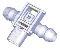 Figure 5. This direct die- mounted monolithic pressure sensor simplifies manufacturing and improves field reliability by eliminating the need for a separate substrate or intermediate chip-level sensor element package. |
|
Several manufacturers have introduced models where the sensor and signal conditioning die are mounted directly into the housing, thus eliminating the cost of a separate substrate (see Figure 5). This is particularly favorable for highly integrated designs, such as the monolithic, single-chip sensor that calls for few or no additional passive components.
Of course, the size of a package is constrained by its contents, and packages promise to get smaller as
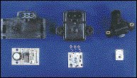 Photo 2. Construction of the most mature automotive pressure application, MAP senosrs, has evolved from PCB-mounted discrete components to simpler hybrid substrates with thick film resistors. The size of these hybrids has been reduced farther through the use of on-chip thin film resistors. |
|
Commercial Considerations
One key consideration in the commercial development of automotive micromachined pressure sensors was the high-volume driver (MAP sensor) that provided a base technology broadly applicable to other pressure sensor products. The design techniques, process capabilities, and installed base of manufacturing capital could then be leveraged to provide a learning curve effect that benefited and accelerated the introduction and growth of products for new applications. The market size for the product driver needed to have sufficiently large unit volume, absolute dollar amount, and profit margin to justify the resource and investment levels necessary to enter the market.
Micromachined devices may act as a key enabling technology for higher value-added products that are strategically important to a subsystem manufacturer. Examples are MAP sensors used for engine control, accelerometers used in air bag systems, and inertial sensors used in vehicle dynamics systems. Micro-fabricated devices can create a "technology nonlinearity" that can provide a supplier with a product development capability that differentiates the supplier from its competitors. Various levels of product integration, such as modules with multiple sensors, or sensors combined with actuators and control capability, also support the trend for subsystem sourcing by vehicle manufacturers.
Conclusion
A view of the evolution of automotive pressure sensor technology clearly shows that a variety of capabilities is required to produce a successful commercial product. Expertise in mechanical packaging; materials science; circuit and systems design; IC design; high-volume trim, measurement, and production organization; and application engineering to fit the end-user system requirements are all important factors that can contribute to a sensor manufacturer's success.
|
The Capacitive Alternative
Capacitive pressure sensing using a bulk micromachined silicon wafer bonded to a glass constraint had some early high-volume success, but gave way to the piezoresistive type as the automotive sensor industry evolved. The size of the capacitive device was not so amenable to die shrink (and subsequent cost reductions) as the piezoresistive type. Generally speaking, capacitive pressure sensing is better suited to absolute, rather than gauge or differential, applications.
|
For Further Reading
Alba, M. Feb. 1989. "The Application of Microcontrollers to Automotive Smart Sensors,"
Proc
SAE International Congress and Exposition.
Czarnocki, W.S. et al. March 1999. "Programmable CMOS Integrated Pressure Sensor," Proc SAE International Congress and Exposition.
Czarnocki, W.S. and J.P. Schuster. 22 May 1994. "Automotive Sensors," Proc COE'94 Conference.
Czarnocki, W.S. and J.P. Schuster. May 1995. "Robust, Modular, Integrated Pressure Sensor," Proc 7th International Congress on Sensors.
Kress, H.J. et al. Feb. 1995. "Integrated Silicon Pressure Sensor for Automotive Application with Electronic Trimming," Proc SAE International Congress and Exposition.
Mahana, P.M. and F.N. Trofimenkoff. June 1986. "Transducer Output Signal Processing Using an Eight Bit Microcomputer," IEEE Transactions on Instrumentation and Measurement , Vol. IM-35, No. 2.