
Jonathan Rowe, Invensys Process Systems, Measurements & Instruments Division
A boiler drum is a vessel where water is converted to steam by the application of heat. For proper boiler control, there must always be sufficient water present in the drum to produce steam and prevent damage to the drum. At the same time, the water level must not be too high, a condition that would prevent the formation of steam in the drum. As demand for steam increases, the feedwater flow rate into the drum must also increase to maintain the water level within acceptable limits. Due to the interaction of the steam flow rate and changing pressure in the drum, the water level can be difficult to control and typically requires sophisticated control techniques. Regardless of the control method selected, for level control to be successful, an accurate water level measurement must be made and transmitted to the control system.
The traditional approach for this level measurement has been to use a conventional differential pressure (DP) transmitter with external water-filled "wet" legs (pipes) connecting the high- and low-pressure sides of the transmitter to the drum. The water-filled legs isolate the transmitter from the high temperatures of the steam and also prevent varying water levels in the legs due to condensation. A separate pressure transmitter also measures the steam pressure in the drum.
Using DP transmitters for drum fluid level is ideal because of their low cost, ease of installation, and high reliability. However, in this application, the output of a conventional DP transmitter will have inaccuracies caused by changes in static pressure and by the changing densities of the water in each leg and of the steam and water in the drum. Although water is normally thought of as an incompressible fluid, water at high pressure experiences density changes independent of those caused by temperature variations.
Traditionally, control system resources are used to calculate the best possible level based on pressure and differential pressure measurements as well as assumptions about the temperatures of the wet legs.
Sensor Solution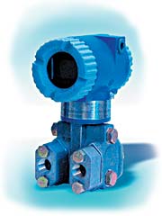
Figure 1. This photograph shows the IMV31 density-compensated level transmitter.
The Foxboro IMV31 density-compensated level transmitter shown in Figure 1 provides a new approach to drum level measurement. While maintaining all the advantages of DP transmitters, its multiple measurements and onboard level calculations provide a more accurate measurement of the water level in the drum while also eliminating the need to make similar level calculations in the control system.
The IMV31 is based on Foxboro's multivariable transmitter technology, which was originally developed for flow measurement. The heart of the IMV31 is its ability to conduct onboard level calculations based on its multiple measurements and fluid density calculations. The transmitter has both a pressure sensor and a DP sensor, as well as two internal temperature sensors. It can also power and monitor an external RTD temperature sensor.
The IMV31 continuously calculates four unique fluid densities, based on measured pressures and temperatures, and uses this information along with the DP measurement to calculate an accurate density-compensated drum level. The densities of both the water and steam are calculated separately, based on the pressure measurement and drum temperature. Although the transmitter has an RTD input, it can also use the saturation temperature corresponding to the measured drum pressure in calculating water and steam densities. Similarly, the densities of the water in each external wet leg are calculated based on the measured pressure and temperatures (see Figure 2).
Figure 2. In this diagram, the term M6 represents the calculated level measurement, referenced to the zero reference point. Dimensions H1, H2, and H3 vary with different installations and are user-entered configuration constants.
The IMV31 transmitter can be configured to use either of its two onboard temperature sensors or an external RTD to independently determine the temperatures of each wet leg. This provides better compensation for changes in water densities in the legs than is possible by assuming a constant temperature for the wet legs (alternatively, the IMV31 can be configured for user-entered constant temperature values as well).
Because the IMV31 transmitter measures both pressure and differential pressure, it can self-compensate for static pressure effects on the DP measurement, a feature that is not available on conventional DP transmitters.
A PC-based configuration program is offered for easy transmitter setup. Tank graphics are provided to facilitate entry of tank and piping dimensions as well as drum and wet-leg pressures and temperatures.
Level-Best Results
Regardless of the size of the drum and the saturation pressure, the multivariable transmitter provides significantly more accurate drum level measurement than conventional DP transmitters and automatically provides dynamic compensation for varying pressures and temperatures.
Let's look at some sample situations:
Example 1. Consider a 300 psi boiler with a 30 in. drum (±15) where level is meas- ured from the midpoint of the range (0 in.) down to -15 in. or up to +15 in. Using a conventional DP transmitter without density compensation, we can expect the following errors during critical startup conditions when the drum pressure is at 50 psi:
When the level is really -15 in., the indicated level would be 0.25 in. too high (0.84% of span).
At 0 in., the indicated level would be 1.1 in. too low (3.7% of span).
At +15 in., the indicated level would be 2.5 in. too low (8.2% of span).
By compensating for the temperature- and pressure-related density changes, the density-compensated IMV31 can reduce these errors to ±0.3% of span or <±0.10 in.
Example 2. Consider a 1000 psi boiler with a 60 in. drum (±30) where level is measured from the midpoint of the range (0 in.) down to -30 in. or up to +30 in. Using a conventional DP transmitter without density compensation, the following errors can be expected during critical startup conditions when the drum pressure is at 100 psi:
At -30 in., the indicated level would be 2 in. too high (3.3% of span).
At 0 in., the indicated level would be 4.4 in. too low (7.3% of span).
At +30 in., the indicated level would be 10.75 in. too low (17.9% of span).
The density-compensated IMV31 can reduce these errors to ±0.3% of span or <±0.20 in.
These examples demonstrate the improvement that density compensation brings to the level calculation and shows how these accurate calculations can be produced right in the transmitter, eliminating the need to allocate system resources to make these calculations. Regardless of the size and pressure rating of your boiler, a multivariable, density-compensated transmitter will deliver the level accuracy you need.
Jonathan Rowe, B.S.M.E., can be reached at Invensys Process Systems, Measurements & Instruments Div., Foxboro, MA; 508-549-6294, [email protected].