

Misdirection
Have you ever noticed that magicians always have a good-looking assistant? It is deliberate and stage magicians know it as misdirection. Misdirection is a form of deception in which the attention of an audience is directed on to one thing in order to distract it from another. The greater the audience's focus on one area, the greater the magician's potential for audacity in another. Unfortunately, for design engineers the encoder industry seems to have learned a thing or two from the magic circle.

Magicians employ a good-looking assistant to misdirect the attention of an audience.
This article can reveal that the industry recognizes that most design engineers do not really understand the difference between resolution, repeatability, linearity, and accuracy. Plenty of design engineers still believe that a rotary or angle encoder with 5,000 counts per rev will be accurate to 1/5000th of a rev. Further, plenty of design engineers will also believe that an encoder with 10,000 counts per rev is twice as accurate as an encoder with 5,000 counts per rev. The encoder industry is happy to let this confusion continue because it is not in the interests of the big optical encoder companies to correct it.
Next page
Terminology
For angle encoders, resolution is defined as the smallest change in angle that can be detected reliably. A true high-resolution angle encoder is one that reliably detects and reports very small changes in angular position. It follows that high resolution encoders will need to have high numbers of counts per rev. Some angle encoders claim to have, let us say, 12 bits of resolution (equivalent to 4096 counts per rev), but fail to say that the last two bits of the output signal are noise.
In such instances, whilst the encoder's electrical output does indeed have 12 bits of data; the two least significant bits (LSBs) are rubbish. This means that the smallest change in angle or position that can be detected by such an encoder is much more than 1/4096 of a rev. Such encoders should really be marketed as true 10-bit encoders. The snag is, 10-bit encoders are priced less than 12-bit encoders. Have a guess what some encoder manufacturers do. That's right, it's called 'specmanship'.
An encoder's datasheet should preferably state resolution along with a second parameter: repeatability. This seldom happens.
Repeatability is a good way to determine the quality of an encoder's stated resolution. For angle encoders, repeatability is defined as the maximum difference in the sensors' output when a measured position is departed from and returned to. Ideally, the repeatability figure should be ±1LSB, indicating a true, low noise output.
For magnetic encoders, repeatability factors are often surprisingly large due to magnetic hysteresis. A high precision angle encoder is one that reports the same angular position with a high degree of repeatability.
Then there is the issue of linearity and accuracy. Accuracy can be defined as an encoder's veracity – in other words the difference between an encoder's output and true position. To most intents and purposes, a highly linear angle encoder is also usually a high accuracy encoder.
Optical Encoders
Optical encoders are the most frequently used form of encoder. They work by shining a light source on to or through an optical element – usually a glass disk. The light is either blocked or passes through the disk's gratings and a signal, analogous to position is generated.
The glass disks are amazing, with tiny features that allow manufacturers to claim high precision. What is often not explicit is what happens if these tiny features are obscured by dust, dirt, grease, etc. For our purposes, we will ignore the issues of obscuration, fragility of the glass, optoelectronics life, and temperature limits since these problems are well understood by most engineers.
Less well known is the issue of mounting tolerances and their relationship to accuracy for optical encoder kits and ring encoders. Consider an optical ring style encoder using a 1" nominal disk with a resolution of 18 bits or 263k counts per rev. In the minds of many design engineers this would equate to an accuracy of 5 arc-seconds. The reality is that such a device will have nothing like such accuracy. We can illustrate this by way of an example. Consider that the disk is mounted slightly eccentrically by 0.001" (0.025mm).
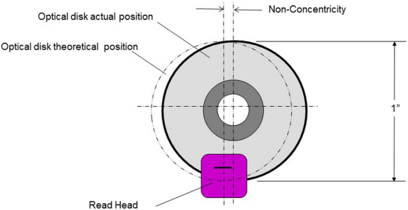
A non-concentric optical disk and read head.
Next page
Eccentricity comes from several sources and the following is a list of just some:
- concentricity of the glass disk on its hub
- concentricity of the hub's through bore relative to the optical disk
- perpendicularity of the hub relative to the plane of the optical disk
- parallelism of the optical disk face with the plane of the read head
- concentricity of the shaft on which the hub is mounted
- clearances in the bearings and bearing mounts which support the main shaft
- imperfect alignment of the bearings
- roundness of the shaft and roundness of the hub's through bore
- locating method (typically a grub-screw will pull the hub to one side)
- displacements due to stresses or strain from forces on the shaft's bearings
- thermal effects
- etc.
A perfectly mounted optical disk requires such fine engineering that cost becomes prohibitive. In reality, there is a measurement error because the optical disk is not where the read head thinks it is.
If we consider a mounting error of say 0.001" then the measurement error is equivalent to the angle subtended by 0.001" at the optical track radius. To make the mathematics easy, let's assume that the tracks are at a radius of 0,5". This equates to an error of 2 milliradians or 412 arc-seconds. In other words, the device is more than 80 times less accurate than first expected, even before any of the inherent inaccuracies of the angle encoder are accounted for.
From experience, I can advise that if you get an optical disk positioned accurately to within 0.001" of an inch you are doing really well. Realistically, you're more likely to be in the range of 2 to 10 thousandths of an inch, so the actual accuracy could well be hundreds of times worse than might have been originally expected.
There's a few ways to combat such problems:
- ensure you understand the important aspects of what is to be measured – whether its resolution, repeatability or accuracy
- study the encoder datasheet carefully and if the important parameters are not stated, then contact the manufacturer or find another manufacturer
- pay particular attention to installation tolerances – these are likely to be in the small print and particularly tight for optical ring encoders and optical encoders kits.
A Different Approach
The measurement principle of inductive encoders (incoders) is fundamentally different to optical devices. Measurement is based on the mutual inductance between the faces of the rotor (the disk) and the stator (reader). Rather than calculating position from readings taken at a point, measurements are generated over the full face of both the stator and rotor.
Consequently, discrepancies caused by non-concentricity in one part of the device are negated by opposing effects at the opposite part of the device. Installation tolerances are often much larger than those stated for optical devices. Instead, realistically achievable tolerances – typically ±0.2mm are often stated for incoders and these tolerances are accounted for in any quoted resolutions, repeatabilities, and accuracies. Further, stated performance for incoders are not subject to variation due to foreign matter, humidity, life-time, bearing wear or vibration.
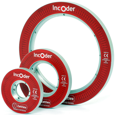
Incoders
Conclusion
In summary, a large number of encoder data sheets will still just state counts or pulses per rev. Such specifications are not necessarily linked to measurement performance. So now you know this stuff, please make sure you don't get fooled next time round.
About the Author
Dr. Darran Kreit is a co-founder and the Technical Director of Zettlex. He co-developed Zettlex's patented new generation inductive technology which is now sold to 38 countries around the world. For further information:
Zettlex UK Ltd
Newton Court, Newton, Cambridge, CB22 7ZE, United Kingdom
Contacts: Mark Howard or Josef de Pfeiffer
Email: [email protected]
Telephone: +44 1223 874444
Web: www.zettlex.com
Related Stories
The Linear Position Sensor Market is Estimated to be Worth USD 4,457.7 Million by 2022
Inspur's Secrets Unveiled Behind Baidu's Driverless Car Technology