|

Like many mechanical instruments, compasses have evolved with technology. Today's electronic/digital compasses use various types of magnetic sensors-such as fluxgate magnetometers and magnetoinductive and anisitropic magnetoresistive devices-to measure the earth's low-level magnetic field. The measurements are then mathematically converted into a directional reading known as azimuth or heading.
Electronic compasses have distinct advantages over their mechanical predecessors. Most notably, they provide a much more accurate indication of heading and can interface directly with various control and navigation systems (see Figure 1).
Gimbaling
The Earth's magnetic field, which is 3D, consists of two horizontal (X and Y) axes and one vertical (Z) axis. For the heading of magnetic sensors to remain true, the X- and Y-axis sensors must remain horizontal, or level. If not, the Z axis is induced into the X and Y sensors, which can translate into heading errors as great as 2º-5º for each degree of tilt from level. In addition, the magnitude of the Z axis varies with geographic location (greater near the poles, lesser at the equator), adding another measurement variable.
The earliest remedy to this problem was mechanical gimbaling. This involved mounting the compass between two rings, which would pivot at right angles to each other. The entire assembly would then be immersed in a damping fluid, typically silicon, to attenuate oscillation effects. When tilted, the compass would remain level, negating the effects of the Z axis. Although somewhat effective, this design had many shortcomings-such as size, shock, and vibration susceptibility; sloshing effects; slow response; and frame-related ferrous effects (i.e., errors)-relegating the compasses to primarily navigational applications. To improve performance and reduce size, the mechanical design elements had to be eliminated.
The ultimate solution to the problem came in the form of electronic gimbaling, also known as electronic tilt compensation. This method uses a dual-axis tilt sensor to measure the X and Y axes' deviation, or pitch and roll, from true level. By combining the tilt-sensor output information with a Z-axis magnetic sensor reading, the X and Y axes' magnetic sensor readings (which determine heading) can be mathematically rotated back to the horizontal plane using rotational algorithms. Once this is accomplished, the heading can be accurately calculated. Although this method requires a third magnetic sensor to measure the Z axis and adds to the overall complexity, the tradeoff is negligible compared with the benefits.
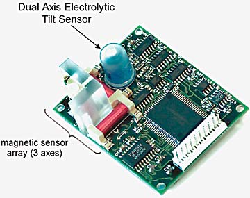
Electronic tilt compensation has become an industry standard. It is commonly referred to as a strap-down solution, meaning that it has no moving parts (see Figure 2).
 Figure 2. Readings from the three magnetic sensors and a dual-axis tilt sensor are delivered to the microprocessor via the A/D converter. Algorithms then mathematically correct for any tilt-induced errors in the X- and Y-axis magnetic sensors, which determine heading. Precise tilt-angle sensing is essential because it affects the accuracy of the heading calculation. |
By eliminating the mechanical aspects of the design, reliability and performance are improved. The method also makes it possible to compensate for nearby magnetic (ferrous) effects, nullifying externally generated accuracy errors.
The Dual-Axis Electrolytic Tilt Sensor
Compass manufacturers prefer to use the dual-axis electrolytic tilt sensor to measure pitch and roll angles primarily because of their low-cost/high-performance ratio and compact size. Electrolytic tilt sensors are AC-operated devices, meaning they require an AC excitation voltage and deliver an AC voltage output. Traditionally, the tilt sensor within a signal conditioning circuit is treated as a voltage divider or ratiometer. This approach normalizes minor changes in excitation voltage and temperature effects. Typical signal conditioning circuits, which operate from DC supply voltages, internally generate the required AC excitation voltage and demodulate the AC voltage output for subsequent processing.
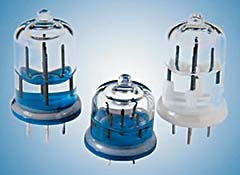
The electrolytic tilt sensor's basic theory of operation is as follows. An electrically conductive fluid (electrolyte) is sealed within a glass or ceramic cavity to conduct between a common, a positive, and a negative electrode. When at electrical null (i.e., level), both electrodes are evenly submerged in the fluid, which remains level because of gravity. This produces a balanced (equal) signal output between the positive and negative electrodes and common. Figure 3 depicts a single-axis tilt sensor
 Figure 3. At electrical null, an electrolytic tilt sensor will have equal portions of the positive and negative electrodes submerged in the electrolyte (fluid). When interfaced with a properly balanced signal conditioning circuit, the output will indicate zero. |
As the sensor is rotated around its sensitive axis, the amount of surface area submerged in the fluid will increase for one electrode and simultaneously decrease for the other, creating an imbalance in the output (see Figure 4).
 Figure 4. As an electrolytic tilt sensor is tilted away from electrical null, the amount of positive and negative electrodes submerged in the electrolyte (fluid) will become larger for one and smaller for the other. The imbalance creates an output signal proportional to the tilt angle. |
This imbalance, or ratio, of one electrode to the other is directly proportional to the angle of rotation.
Electronic gimbaling requires dual-axis tilt sensing, so two sets of electrodes are required. The second set of electrodes must be accurately positioned, perpendicular (orthogonal) to the first set.
When looking at the composite heading error for a typical electronic compass system, the magnetic sensors themselves are surprisingly minor contributors. This is because most of their errors (linearity, hysteresis, repeatability, noise, and ferrous effects) are normalized during the calibration process, rendering them insignificant. Temperature effects, though considerable, are generally secondary. The tilt sensor will normally be the largest contributor, accounting for roughly half of the total error. Therefore, any improvements to tilt sensor accuracy will have a direct effect on compass accuracy.
|