

Operating environment plays a major part in the ongoing operation and accuracy of pressure transmitters. If not properly specified to handle environmental conditions such as sub-arctic locales and freezing liquids, pressure transmitters can fail prematurely and cause catastrophic failure to equipment.
While pressure transmitter specification sheets provide information regarding sensor performance at ambient conditions, expected readings over a given temperature range, as well as various terms and acronyms clarifying how the pressure transmitter will perform in different conditions, a deeper understanding of the construction of the transmitter will help define how the sensor will perform in extreme environments, particularly in cold temperatures.
Pressure transmitters typically use some form of strain gages mounted to a diaphragm to measure pressure. These gages can be applied using glue, thin film deposition, encapsulated in oil, or mounted using a glass firing process. As the diaphragm deflects, the resistance values change. In all cases, the effects of temperature can also change the resistance of this output signal, causing errors in the sensor.
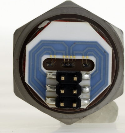
Fig. 1: Strain gages on a diaphragm of a pressure transmitter.
Next page
Sensor survivability can be tested in cold weather climates. Temperatures below -20°C (-4° F) can cause oil-filled sensors to gel and harden. With ceramic technology, the O-ring between the machined port and diaphragm can harden and become brittle. This compromises the integrity of the sensing element and creates a potential leak path. To prevent the sensor from reaching below its operating temperature range, their location and environment must be altered. Heated boxes or rooms can be used to protect the sensor as well as prevent the temperature at the sensor from reaching freezing temperatures.
In remote locations, power may not be readily available for instrumentation operating from solar power. Thus, the ability to heat the sensor is limited or not available. For example, well equipment in Alaska, Alberta, British Columbia, Saskatchewan, and North Dakota can experience temperatures as cold as -50°C (-60°F) where sensors are installed outdoors directly on piping to monitor hydraulic, casing and tubing pressure from the well head.
Freezing of Process Media Effects Sensor Operation
Icing of process media is an indirect result of cold climates. In certain natural gas drilling applications, water can be found in the same pipes as the gas. When the system is shut down and the temperature drops below freezing, the water inside the pipe can freeze and expand, causing an overload on the pressure sensor for a prolonged period of time. The expansion can mirror a pressure spike of 500 PSI (35 bar) to 1,000 PSI (70 bar) of pressure. For a 100 PSI system, the pressure can increase to 1,500 PSI (100 bar).
For many sensor technologies, this strain on a lower pressure diaphragm will cause a failure of the strain gage or rupture of the diaphragm. To protect against sensor failure, the pressure increase must be sustained by the sensing element for a period of time without affecting the accuracy of the sensor after thawing. Special cavity design as well as special proof pressure capability and calibration are the best ways to guarantee that the sensor will not fail from the media freezing in the cavity.
Next page
How to Compensate for Temperature
In order to compensate for the changes in temperature electrically, pressure transmitter manufactures test sensors over both pressure and temperature to adjust for the effects of temperature. Because each sensor and strain gage is unique, it is best practice to test each individual sensor for its specific properties.
The traditional method is to trim, or reduce, the raw output signal using resistors to optimize performance over the tested temperature range. The sensor would, then, use a circuit board assembly that amplifies the millivolt signal to the required output signal (ex. 4-20mA). Certain pressure transmitters will offer zero and span adjustability. This function is commonly needed for drifted output signals after diaphragm fatigue.
As the cost and size of digital electronics have decreased, there has been an increase in the usage of digital compensation through the use of an ASIC (Application-Specific Integrated Circuit). In cases of low temperature, the ASIC is programmed as the pressure sensor is tested over temperature, with some designs correcting non-linearity, or deviations from the ideal output signal. The temperature of the ASIC can be compensated at the gages, using a temperature sensor such as a thermistor or at the ASIC itself. The main difference is media temperature. If compensated based on the ASIC temperature, the temperature reading is not as accurate due to its proximity to the media. In cold climates, the ASIC could be reading close to ambient temperature, whereas the media could be a hot liquid or gas. Measuring the temperature of the gages produces the fastest response and dynamic compensation, optimizing performance.
Another manufacturing advancement related to pressure transmitters is the ability to offer an independent temperature output signal. System integrators can now closely monitor the changes in media temperature from a single device, reducing the cost of installation and the cost of the additional sensor.
Referring to the photo (see figure 2), you'll observe a one piece, stainless steel sensing element that is machined so there are no welds or internal O-rings. Since there are no welds or joints in this design, fatigue value is much lower over a wide operating temperature.
x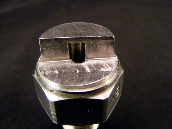 x
x
Fig. 2: A one piece stainless-steel sensing element machined to eliminate welds and/or internal O-rings.
Constructed of very thick diaphragms and state-of-the-art silicon strain gages, these explosion-proof pressure transmitters offer repeatable results even in the hostile environs of deep well drilling (see figure 3). The addition of a Waspalloy material option, in addition to Inconel 718, 17-4 PH, Hastelloy C-276 and 316 L SS wetted parts, further extends these pressure transmitters' use in the processing of heavy oil and high sulfidation.
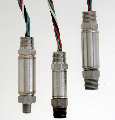
Fig. 3: Explosion-proof pressure transmitters suitable for use in dangerous environments.
About the Author
Greg Montrose is the Sales and Marketing Analyst at American Sensor Technologies, a TE Connectivity company. With ten years of experience in instrumentation and controls, he has worked in both sales and marketing functions supporting various industrial, aerospace, alternative energy, and hazardous location projects and applications.
Related Stories
Pressure People Ponder and Predict, Part One
Pressure People Ponder and Predict, Part Two
Pressure People Ponder and Predict, Part Three
Pressure People Ponder and Predict, Part Four, Finale