
Typical rapid transient electrical applications, or voltage spikes, are fast, short-duration electrical changes in voltage (voltage spikes), current (current spikes), or transferred energy (energy spikes) within an electrical circuit. In many cases, an engineer or test technician may only have a single viable opportunity to capture the necessary diagnostic data from such an event to prevent damage to machinery, systems, and equipment. In many cases, improper data collection could add significant costs (in the range of millions of U.S. dollars) to the project and also potentially cause significant personal injury. As such, this very short-duration event requires a high-speed, high-accuracy, isolated DA system for safe, accurate, and reliable measurements.
Whether the measurement system is used to help protect spacecraft from prelaunch lightning-strike damage or to ensure the continuous operation of a major power grid, it is essential for an engineer to understand the demands and risks involved in taking the measurement, the ultimate testing goals, and the suitability of the specified hardware and software for meeting such objectives.
At the time of measurement, rapid transient electrical applications may include the presence of naturally-occurring high-voltage conditions, such as those created by a cloud-to-ground lightning strike. Other such considerations include extreme low and high temperatures; the presence of humidity, moisture, dirt, dust, and other contaminants; and the risk of equipment exposure to inclement weather conditions. These conditions create the need for a system that is sufficiently electrically isolated for user safety and the prevention of equipment damage, rugged enough to withstand aggressive outdoor conditions; and one that also demonstrates high accuracy at extremely high speeds. This article presents a series of considerations and application examples concerning the successful implementation of such ultra high-speed DA devices.
Lightning Strike Protection
A naturally occurring electrical discharge, lightning travels at different speeds and voltages, depending on the conductivity of the medium through which it is traveling. The U.S. Department of Energy has reported the speed of lightning as 93,000 miles/s, with other estimates as high as 9,000,000 mph. The speed of lightning at the time of detection also may be affected by its overall stage of detection. For example, a downward lightning strike tends to travel more slowly than its corresponding returning upstroke. Potential lighting-strike damage can take <1 s to occur, with resultant damages to critical systems and equipment taking months or years to repair.
With its proximity to the equator, NASA Kennedy Space Center in Cape Canaveral, FL, is an ideal location for launching both manned and unmanned spacecraft and future-generation rockets. The earth's natural rotation at that point provides spacecraft with an extra natural upward push, which ultimately reduces the fuel required to effectively power spacecraft above the earth's atmosphere. At the same time, Kennedy Space Center is plagued by one of the highest rates of ground lightning strikes per square kilometer in the U.S. In 2009, it was estimated that the NASA Space Shuttle Endeavour launch pad area was struck a minimum of eleven times on the lightning mast and water tower, leading to costly launch delays. Thus, lightning is considered a formidable risk to spacecraft launch operations, as the vehicles are highly vulnerable to damage caused by high strike-induced currents and voltages.
Spacecraft are initially assembled inside the large Vehicle Assembly Building and transported to the launch pad on special heavy-duty transporters, or Mobile Launcher Platforms, for final prelaunch preparations and mission checks. A spacecraft is vulnerable to lightning strike damage from the moment it emerges from the Vehicle Assembly Building until final launch. During this time, it is important to continuously monitor numerous measurement points to identify any potential for negative induced area effects.
To ensure the safety and effectiveness of such launches, NASA designed its own proprietary lightning monitoring system that incorporates HBM's DA system technology. Using a series of high-precision transient recorders and digitizer transmitters, the system works alongside a secondary lightning protection system, with both components up and running at each spacecraft launch point. Design of the NASA Kennedy Space Center lightning protection system also incorporates the use of tall towers that support metal cables that can intercept lightning strikes and divert the resultant electrical current away from the spacecraft launch vehicle. Two launch pads, in particular, were designated for protection in the testing area: Launch Pad 39A, used during active manned Shuttle launches, incorporated one lightning protective device on top of the pad, while Launch Pad 39B, designed for next-generation launches, features three 180 m high lightning protection towers.
Because of the high shock and vibration levels and ambient temperatures typically present during launch, the system had to meet specific MIL-SPEC standards. In addition, the transmitter input had to be solely DC-powered with the ability to effectively switch to battery operation and complete system isolation while lightning was in the area. Equally important was the ability to switch to a DC charging circuit via remote control after thunderstorms for continuous system monitoring.
Working with NASA, HBM incorporated the Genesis HighSpeed, high-resolution DA system with Perception software (Figure 1) to facilitate the review, control, and analysis of captured induced current and voltage data at various points, with 0.1% F.S. accuracy and 25 MHz bandwidth. The system was housed in a corrosion-resistant 304 stainless steel enclosure for protection from Florida's humidity, moisture, and environmental contaminants. Fiber-optic cables supported a distance of up to 12 km between numerous measuring points. IRIG time codes were used to synchronize data between multiple mainframes. Fiber-optic transmitters were linked to a receiver accepting up to four transmitter signals for single-mode fiber-optic transmission and 900 Megasamples of memory. Each measurement point included a remotely controlled test-signal source for signal path verification with the ability to analyze and automatically generate reports detailing the unique characteristics of each lightning event. Effective multipoint monitoring allowed engineers to identify locations where high induced currents may have occurred due to lightning-induced rapid transients.
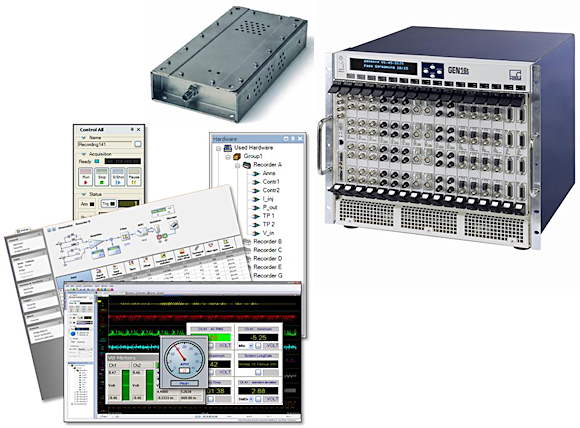 Figure 1. The Genesis HighSpeed, high-resolution DA system with Perception software |
By incorporating this specialized technology, NASA was able to equip Kennedy Space Center with an effective lightning-strike monitoring and protection system that significantly reduced launch delays by quickly identifying any potentially negative local electrical effects induced by area lightning strikes. The new system also helped to ensure the best possible spacecraft prelaunch conditions, while eliminating the possibility of further damage caused by rapid, single-shot lightning strikes.
High-Voltage Impulse Testing
The risk of lightning-strike damage to machinery and equipment is not limited to the U.S. space program. Such meteorological phenomena also pose significant risks for utilities and municipal power grids. Damages to power masts, generators, or even to the grid itself, can result in unplanned power outages, costly and unpredictable downtime, and grid blackout conditions.
In most cases, electricity is not produced at the same location where it is consumed. The power grid serves as the primary infrastructure by which power plants transport electricity to both commercial and residential end users. Most power grids exist in the form of power lines installed on towers with lines organized into levels based on their required power transport capacity: low-voltage (LV) is 100 V and up to about 600 V; medium-voltage (MV) is >600 V and up to about 100,000 V; and high-voltage (HV) typically exceeds 100,000 V. The levels are interconnected by a series of substations that rely on transformers, circuit breakers, surge arrestors, isolators, switchgear, and other equipment to ensure safe and reliable electricity transport. The intricate nature of the power grid setup leaves supporting substation components vulnerable to lightning strike damages. With hundreds of thousands of utility customers linked within a single grid, the use of effective lightning test equipment is essential for sustained, continuous, and efficient grid operation.
For component manufacturers involved in power-grid design and development, an associated challenge is the need to develop a rigorously tested, highly rugged end product that can successfully withstand power grid conditions. This requires proper quality assurance testing and certification of transformers, surge arrestors, isolators and switchgear for their high-voltage survivability.
Globally recognized testing standards describe proper high-voltage test setups and associated test procedural steps, as well as the types of specific hardware and software specified for accurate, repeatable data collection and results. High-voltage component testing requires specialized equipment, capable of producing lightning waveforms with known wave shapes and peak voltage levels of up to several MV. On the other side of the test object, equipment also must be able to measure the wave shape and evaluate all relevant parameters according to the appropriate standards. The more accurate an initial measurement, the greater the likelihood that a manufacturer can avoid component under- or over-testing.
Efficiency is another important aspect of optimal power-grid component testing. For example, a three-phase transformer tested on all six phases/bushings (three inputs and three outputs) on a number of voltage levels and for a number of different waveforms can easily result in 50 to 100 shots per test object. All waveforms are then analyzed and documented within a report.
The incorporation of the ISOBE5600t/m (Figure 2, see "A DA System for High-Voltage Impulse Component Testing" below) and other HBM DA systems enables the seamless integration of new high-voltage grid systems and components and the upgrade of legacy systems, with added safeguards for continuous, uninterrupted power service. HBM DA systems are also used to support next-generation Smart Grid technology development by providing a reliable means to test newly developed infrastructure.
 Figure 2. The ISOBE5600t/m high-voltage, fiber-optic-isolated DA system with proprietary Lightning Impulse Analysis software |
Circuit-Breaker Interruption Detection and Monitoring
Traditional circuit-breaker systems operate on the premise of electrical contacts moving away from one another, creating an electrical arc. The measurement of interruption phenomena that affect breaker performance and operation is known as circuit zero (CZ). CZ measurements are commonly used as a research tool to understand and improve the mathematical model of the electric arc, while identifying dominant parameters for successful current interruption, such as pressure, temperature, ion density, and plasma flow. This leads to improved circuit breaker design and greater interruption capability.
Circuit-breaker manufacturers often rely on the services of third-party test laboratories for CZ testing to ensure that their finished products have been correctly assembled and will operate according to the manufacturer's published specifications. The external test house acts as a credible, independent authority between buyer and seller, verifying product performance according to manufacturers' published specifications, with a buyer identifying individual specifications of interest. While international testing standards for circuit-breaker final products are well established, CZ testing standards can vary.
KEMA CZ Test Program
Located in Arnhem, the Netherlands, the KEMA High-Power Laboratory has established its own fully dedicated and standardized CZ test program and is considered one of the world's leading experts in high-power acceptance testing.
To support typical CZ testing requirements, a fiber-optic-isolated digitizer, such as the HBM GEN 6600 HV, is placed as close as possible to the test article to minimize analog cable lengths and ensure best results. The digitizer must also be able to deliver signal quality conditions for safe performance, as can be found within the existing KEMA system. Important DA system performance attributes for CZ testing include:
- High dynamic range—currents in the order of 100 mA should be measured immediately following the interruption of many tens of kA of short circuit current.
- Bandwidth—while the main application frequency range is typically only 50 or 60 Hz, other relevant processes occur on a sub-microsecond scale.
- Vertical resolution—this refers to the ADC resolution within a DA system. The higher the vertical resolution, the better an analog signal can be either resolved or vertically reconstructed. An 8-bit ADC provides 28 or 256 levels of vertical resolution whereas a 14-bit ADC provides 214 or 16,384 levels of vertical resolution, a 64-fold increase in resolution over the 8-bit ADC.
In addition, high-voltage transients often contain intense electrical fields of 100 kV/m and magnetic fields of 100 A/m, enough to stop most digital instruments in their tracks. A rugged and well-shielded enclosure can greatly reduce the level of electrical and magnetic fields entering the DA system to ensure proper equipment operation when acquiring transient test data.
A typical acceptance test is designed to verify proper system operation under severe product operating conditions. A system's ability to pass under the worst possible conditions implies that its operation under less severe conditions, such as those occurring during medium- and low-voltage tests, will likely not cause any significant problems. The HBM GEN 6600 HV fiber-optic digitizer was fully tested by KEMA for such durability and passed at all levels of acceptance testing, including extreme conditions, making it a viable option for high-voltage or CZ-related testing requirements.
Switchgear Testing
Switchgear testing requires the use of equipment that can effectively measure low-, medium-, and high-level energy values on an as-needed basis, with each requiring different isolation capabilities. The system must also be able to offer accurate sequencing and timing control, so that if a failure occurs within one segment (e.g., a short circuit due to component breakdown) the rest of the grid may be protected by disconnecting the failed segment and interconnecting all remaining, active segments.
Within this type of testing, currents on the order of hundreds of thousands of amps must be interrupted while voltages of several hundred thousand volts are still present. Thus, hardware must have isolation capabilities and excellent electromagnetic field immunity and offer battery-powered operation. Successful switchgear testing requires the use of a DA system, battery-operated fiber-optic isolated-digitizer, test sequencer, and supporting analysis software, along with appropriate voltage protection for personnel and equipment. Due to the complexity and dangers associated with this type of testing, customers are recommended to source all components from a single manufacturer, to ensure system compatibility, experienced technical support, and the necessary system calibrations.
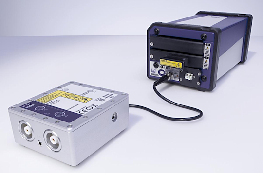
The HBM Genesis HighSpeed DA system has been used effectively to support high-voltage switchgear testing. In addition, the 6600 MV fiber-optic digitizer system offers an isolated power supply and small battery setup for medium-voltage testing requirements. To support the high-speed test sequencing requirements commonly encountered within switchgear applications, the fully fiber-optic-isolated BE3200 (Figure 3) is also ideal, due to its fully user-synchronized timing pattern to the main generator, achieved either via the external mains or derived from an internal timer, and application specific extensions.
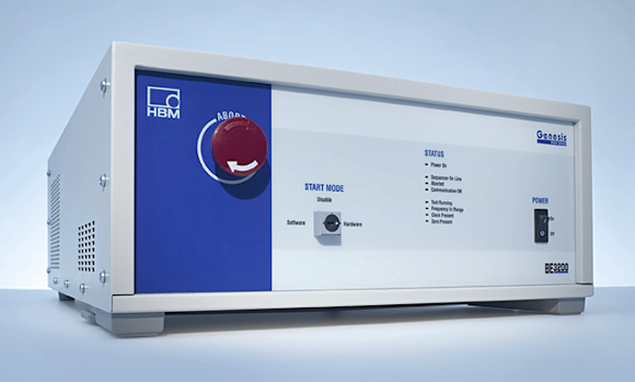 Figure 3. The BE3200 test sequencer |
All HBM switchgear monitoring system hardware and software components are fully compliant with international high-voltage testing community regulatory and safety standards, with proven software designs, and algorithms developed according to globally accepted practices.
|
A DA System for High-Voltage Impulse Component Testing For challenging automated high-voltage impulse component test setups, HBM offers the ISOBE5600t/m, a high-voltage, fiber-optic-isolated DA system with proprietary Lightning Impulse Analysis software, designed to meet industry high-grade reference digitizer standards. Impulse attenuators (Figure 4) interface between customer voltage dividers and the ISOBE5600t/m transmitter input. The Lightning Impulse Analysis software evaluates captured data; tests for overshoot, oscillations, and chopping; performs limit checks; and allows for automated test sequence storage. The software also allows for the storage of test waveform data and results for further analysis and automated reporting. A user-selectable limit checking feature increases testing efficiencies. The ISOBE5600t/m lets users test several phases or bushings at both positive and negative polarities, as well as different voltage levels, for up to 100 measurements per test object. Test collections allow for individualized per-test-object measurements that are brought into the same report for process optimization. A manual accept/reject verification is available after each measurement for real-time accuracy checks. Each test, whether a single measurement or a full data collection, is automatically available in the report generator. The user defines the report layout one time and gets test results, including Pass/Fail indication, in one click of a button.
|
ABOUT THE AUTHORS
Mike Hoyer is an Applications Engineer for HBM Inc., Marlborough, MA. He can be reached at 800-578-4260, [email protected].
Molly Bakewell Chamberlin is President of Embassy Global LLC, in Buffalo, NY. She can be reached at 800-309-6150, [email protected].