

The non-contacting measuring principle of Hall-effect sensors in CMOS technology has proven its worth in automobile electronics for many years. For example, relatively simple Hall sensors with switching output detect if a car door is fully closed or not.
On the other hand, Hall sensors with linear output are used to detect the accelerator pedal position. This parameter is needed for the electronic control of the combustion process and must be detected reliably and with ultimate accuracy. The magnetic field measurement using Hall sensors is highly robust, although the measurement result is influenced by the crystal temperature of the silicon semiconductor chip ("die"). To compensate this factor, the junction temperature will be determined first. This will function best if the temperature sensor is integrated in the same die which also houses the Hall plate.
However, this integrated temperature sensor is exposed to production tolerances – with the ultimate effect that the sensor also needs to be checked. Once the semiconductor has been manufactured, a test phase is therefore carried out where a constant external test temperature is selected and compared with the values of the temperature sensor.
A linear function can be determined in order to balance the ambient temperature and the junction temperature. To be on the safe side, this process is usually carried out at two different temperatures. The constant external temperatures allow the simultaneous measurement of the Hall element by applying a highly accurate and well known magnetic field and detecting the response of the Hall sensor.
Since the 1980s, measurement tasks in automobile applications have been successfully solved with the help of Hall sensor ICs. But the requirements in terms of the reliability of the position data obtained have increased tremendously over the last years. For example, it may be relatively non-critical if a sensor fails to detect an open car door, but detecting an incorrect accelerator pedal position may lead to dangerous driving situations. To enhance safety, there is the option of using not just one, but two sensors for the same measurement. The output signals of both sensors can so be compared and error deviations can be detected. The on-board electronics is now capable of responding accordingly.
The Redundancy Principle
This so-called redundancy principle is one of the best known methods for safety-critical sensor applications. Additional sensors may increase the weight of the application and will also require more installation space, but this problem can be solved by increasing the integration density of the sensors. A method commonly used in the semiconductor industry involves the integration of several CMOS semiconductor chips in a single package. However, this is a novel approach in Hall effect sensors.
The two semiconductor chips may be arranged differently inside the package. One option is to mount both dies side by side on the lead frame of the package. The disadvantage of this solution is that the Hall plates of both chips are positioned differently and will therefore not detect the same magnetic field range. This results in errors of measurement between the two chips and leads to problems in the plausibility check of the redundancy function.
Next page
A Solution
To avoid this effect, it is preferable to arrange the two semiconductor chips one on top of the other (stacked dies). One possibility is to mount one semiconductor onto the top surface of the lead frame and the other semiconductor onto the bottom surface. This does not really comply with the standard setup and calls for new production machines and methods. The reliability of the bonding and connecting techniques must be safeguarded and maintained throughout the life of the car.
Direct bonding of the semiconductor chips has delivered the best results. The wire-bonding connections – mainly those of the bottom die – are of crucial importance. To permit electrical contact, a spacer (interposer) is placed between top and bottom die. After bonding both dies and the interposer, both the bottom and the top die can so be safely wire-bonded (see figure 1).
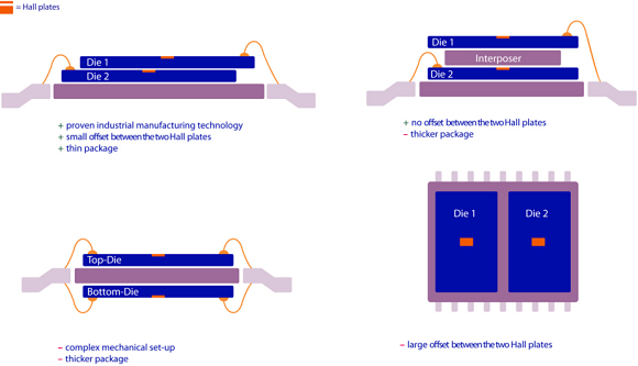
Fig. 1: Different superstructure variants of dual-die Hall sensors
The interposer requires extra space inside the package and causes higher costs. Applications with a small air gap between sensor and magnet (e.g. in the accelerator pedal application) require a flat package. To realize this, it is better to bond the two semiconductor chips directly on top of each other without an interposer.
A minor offset between both dies will allow the bottom die to be bonded without any problems. The outcome is now a small 5 mm x 4.5 mm sensor IC which includes two independent dies. As each die has a Hall plate and a temperature sensor, there is now a total of four sensors in a single package.
Figure 2 shows the inside of a dual-die sensor from Micronas' HAR 24xy product family. It shows the two redundant silicon dies which are offset and bonded on top of each other. The AEC-Q100 qualified sensors are therefore equipped with a redundancy function – hence the description HAR. The sensor is especially suitable for applications involving accelerator pedals.
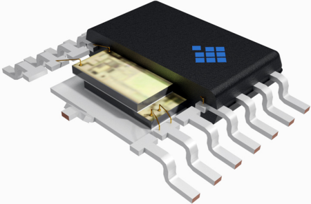
Fig. 2: Hall sensor from the dual-die product family HAR 24xy by Micronas in a TSSOP14-package
Next page
How To Realize Redundancy In A Hall sensor
To guarantee full redundancy, both sensor units must function electrically and mechanically independent from each other. A sensor unit consists of a semiconductor chip with integrated Hall plate to measure the magnetic field strength and one temperature sensor. Separate bonding wires on additional pins will fully separate the voltage supply (VDD) and ground (VSS) of both dies. The outputs are also separately bonded on the individual pins.
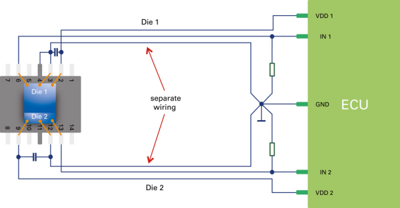
Fig. 3: Wiring option for analysing the sensor data
To enhance safety even further, the pins of both dies are located on opposite sides of the package. The semiconductor chips themselves are electrically isolated from each other through the use of an insulating bonding material. The independently gained measurement data is transmitted to the processing control unit (ECU). Owing to the full electrical isolation, data analysis in different ECUs is also a possibility.
Further uses of the dual-die sensors
There are many applications where the advantages of dual-die sensors of a very small and – above all – flat package can be used. Instead of using the redundancy function, there is also the possibility to realize a measuring range extension. Current sensors using the magnetic field of a live electrical conductor for measurements must be capable of measuring both very small currents and very large fault currents with accuracy. If, as in the HAR 24xy sensors, both dies can now be calibrated separately on different magnetic field measuring ranges, there is now a space-saving and cost-effective solution available, for instance for measuring battery charging currents.
About the Author
Vita Thilo Rubehn is the Head of IC Architects for Micronas in Freiburg. He holds an engineering degree from the Leibnitz University of Hannover and a Master of Science from the University of Arizona. Prior to joining Micronas, Vita worked many years as a mixed-signal designer and project leader.
Related Stories
Eight-inch sensor chips from Infineon could reveal the mysteries of the universe
Magnetic Sensors Market Worth $3.65 Billion By 2022
Disruptive Technology Yields Unique Magnetic Latch/Switch Family with Lateral Sensitivity
Hall Effect Current Sensor Market Worth 1.10 Billion USD by 2020