
Geothermal power shows promise as an environmentally friendly source for electricity generation not least because fossil fuel alternatives produce at least an order of magnitude more carbon dioxide and consume a hundred times more water per kWh of energy produced. Geothermal energy plants have traditionally been limited to the edges of the tectonic plates but recent advances in enhanced geothermal systems (EGS) should greatly expand its geographical range [1].
Critical to successful and reliable EGS operations [2] is improved subsurface visualization. Fiber-optic distributed temperature sensing (DTS) enables both subsurface visualization and understanding of fracture distribution during both fracturing operations and production. The same DTS system can be used for reservoir characterization and management, production optimization, surface and subsurface integrity monitoring, fluid injection and short-circuit monitoring.
This article provides summaries of geothermal energy technology and DTS technology, followed by a discussion of the many applications of DTS to geothermal electricity production.
Geothermal Energy Technology
Traditionally, geothermal power plants have been located in areas along tectonic plates where hot springs and other indications of thermal activity can be seen at the surface (Figure 1). However, EGS can be used in areas where hot rock can be found at reasonable depths; well depths of between 4–6 km would allow EGS in many parts of the U.S. Wells are drilled into the hot subsurface rock; fluid is then injected, heated by contact with the hot rock, and removed to power turbines at the surface.
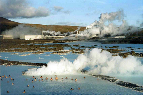 Figure 1. Blue Lagoon, Iceland. Hot springs with geothermal plant in the background. Image courtesy of the Geothermal Energy Association, "Geothermal 101: Basics of Geothermal Energy Production and Use." |
Geothermal energy—thermal energy stored in the ground that is available as either steam or hot water—is converted into electricity by various conversion technologies based on steam turbines. Conversion plants that use a hot water heat source must expand the liquid to a high-pressure vapor/steam form that is then used to mechanically turn a generator turbine. Because geothermal plants use water heated naturally in the earth to produce steam it is not necessary to burn any fossil fuels to generate electricity.
There are three different types of conversion technologies—dry steam, flash, and binary-type—and geothermal power plants typically use just one or a combination of two of these technologies. The type of conversion technology used depends on the state of the fluid (steam or water) and its temperature. Dry steam plants (Figure 2) use a direct flow of geothermal steam and represent about 40% of U.S. geothermal electricity production. Flash steam power plants are most common, with a 45% market share, and typically require resource temperatures in the range of 350°F–500°F. The remaining 15% consists of binary-cycle power plants (Figure 3) using thermal fluids between 165°F to 350°F [3].
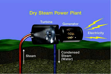 Figure 2. Diagram of a dry steam plant showing its basic operation. Image courtesy of the Geothermal Energy Association, "Geothermal 101: Basics of Geothermal Energy Production and Use." |
 Figure 3. Diagram of a binary power plant. Image courtesy of the Geothermal Energy Association, "The State of Geothermal Energy, Part II: Surface Technology." |
In order for EGS to operate efficiently and to provide competitively priced electricity, a number of parameters and conditions within the well need to be managed because the plant's efficiency is directly related to the amount of thermal energy that can be retrieved from the reservoir. The subsurface reservoir must be able to provide quality geothermal fluid (i.e., a fluid that maintains a high or expected temperature over the life of the asset) in sufficient quantities over the service life of the asset. A fracture network between injector and producer wells must be available or must be created by hydraulically fracturing the hot rock. The produced geothermal fluid is re-injected to maintain reservoir pressure and to extend the service life of the reservoir, so it is critical to understand where the injected fluid goes in the injection well and where in the production well the geothermal fluids come from. It is also desirable to have a large-volume fracture network between the injector and producer wells to allow the fluid to absorb the maximum amount of heat as it migrates from the injector to the producer. A short circuit, i.e., a big channel between the injector and producer, allows the injected water to reach the producer without absorbing heat.
Fiber-Optic DTS Technology
A fiber-optic-based distributed temperature sensing (DTS) system consists of a DTS unit containing one or more lasers, an optical receiver, and a data processing module and a fiber-optic probe up to 20 km in length.
 Figure 4. Basic DTS system schematic showing a snapshot of the backscattered light (A), the equation used to calculate the temperature distribution along the fiber (B), and the resulting temperature profile (C) (Click image for larger version) Figure 4. Basic DTS system schematic showing a snapshot of the backscattered light (A), the equation used to calculate the temperature distribution along the fiber (B), and the resulting temperature profile (C) (Click image for larger version) |
 | (1) |
where:
| R(T) | = | temperature as a function of the ratio of Stokes to anti-Stokes components |
| IAS | = | intensity of anti-Stokes light |
| IS | = | intensity of Stokes light |
| λS | = | Stokes wavelength |
| λAS | = | anti-Stokes wavelength |
| h | = | Planck's constant |
| c | = | speed of light |
| υ' | = | wave number separation from the pump wavelength |
| k | = | Boltzmann's constant |
| T | = | absolute temperature |
| Δa | = | differential optical attenuation between Stokes and anti-Stokes frequencies |
| z | = | distance along the optical fiber |
This is then translated into a temperature trace (Figure 4C) using time-of-flight information. Because the speed of the light traveling in the fiber is known, measuring the time delay between the transmitted pulse and the reflected light allows the calculation of how far the light pulse has traveled along the fiber. After the pulse is transmitted into the fiber, the Stokes and anti-Stokes intensities are measured with a 100 MHz sample rate (equal to a 1 m sample spacing between temperature points) and the temperature is calculated for each sample point.
Raman-based DTS is the most common distributed monitoring technology, with widespread adoption across oil & gas, electrical utility, fire detection, and many other industrial applications. The subsurface conditions in geothermal wells are very similar to the subsurface conditions encountered in heavy oil applications where high temperature steam is injected into tar sand reservoirs to allow the oil to be extracted.
Multiwavelength DTS technology, such as SensorTran's PerfectVision, offers state-of-the-art DTS performance with extended service life, accurate data, and automatic trace-by-trace calibration [4]. A portable DTS system is shown in Figure 5.
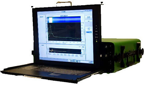 Figure 5. A portable DTS system |
DTS systems can be combined with other sensors, such as pressure gauges, to provide a more comprehensive data set. Fiber-optic sensors offer reliable subsurface/downhole operation up to 570°F; typical electronics experience reliability and service life issues around 250°F–350°F.
DTS in Geothermal Energy Applications
It is well documented that improved subsurface visualization during exploration and production results in more successful and reliable EGS operations [2]. Fiber-optic sensing enables real-time monitoring of subsurface temperature and pressure and this information can be used to:
- Estimate the production potential in or between new wells by measuring the distributed temperature (temperature at every meter along the full depth of the well) and the point pressure, or pressure measured at the bottom of the well. When the operator opens the tap at the surface and allows the fluid in the well to flow, the bottom hole pressure will change. The rate at which this pressure changes in relation to surface pressure or flow changes allows the calculation of reservoir size, flow resistance between wells (if multiple wells are instrumented), well bore damage caused by drilling, the effectiveness of the fracturing operations, and well completion. Draw-down and pressure buildup tests map real-time temperature and pressure data vs. time and production volume providing information on what zones and fractures are producing hot fluids, and how production impacts the pressure within the reservoir.
- Monitor fracture development during stimulation and fracturing. When drilling a well, crushed bits of rock are circulated to the surface by the drilling mud. Although the drilling mud is optimized to lift out as much as possible of the rock and debris from the well, it may plug the pores in the rock and inhibit fluid flow. To remove the drilling mud residue, acid or other fluids may be injected, a process called stimulation. DTS can detect temperature changes when fluids flow to fill the volume as the new fracture opens up.
- Monitor chemical injection during or after a fracturing job, identifying where the chemicals go during a treatment and what zones and fractures take up the chemicals.
- Monitor surface and subsurface scale buildup and chemical clean-up. Scale, a mineral residue precipitated from the geothermal fluid in response to changes in water pressure and temperature, builds up on the pipe walls and will, over time, form a thick, insulating layer that will limit flow and may block a pipe. Chemicals are injected into the pipe to remove the accumulated scale. By understanding the severity of the scaling, operators can better consider what mitigation options are most suitable as well as minimize the use of expensive chemicals.
- Provide permanent monitoring of injector and producer wells to allow identification of the specific zones and fractures that produce fluids. Short-circuiting can easily be detected and mitigated.
- Perform integrity monitoring for casing and tubing leaks to avoid contaminating ground water and subsurface aquifers. This is also applicable to surface piping; additional DTS channels can be added at a minimal cost.
Having a DTS installed at a geothermal plant site offers additional monitoring opportunities. By combining temperature data with subsurface point pressure data, reservoir engineers can update asset models and optimize the efficiency of the geothermal power plant. DTS channels can also be added to monitor surface processes, processes inside the plant, and transmission lines leaving the plant. It is common to de-rate power cables (transmission lines) to 70%–75% capacity to avoid overheating the cable because overheating a power cable will lessen its service life and in some cases cause system failures, with the resulting loss of revenue and infrastructure. Localized overheating caused by hot spots can be detected using a DTS system and the hot spots mitigated. Finally, monitoring the temperature distribution in power cables allows load utilization of up to 95%–100%. Careful design and DTS monitoring technology enable substantial savings in OPEX (operational expenditure) and CAPEX(capital expenditure) in geothermal plants.
Closing Thoughts
Geothermal energy is one of many energy sources of the future, providing cost-effective, environmentally friendly electrical base-load capacity for decades to come. Fiber-optic sensing is a proven technology capable of providing subsurface and surface measurements at temperatures up to 300°C. The temperature and pressure data acquired provide subsurface information for real-time visualization of geothermal reservoirs. This information can be used for production optimization and reservoir modeling. For these reasons DTS is a key monitoring technology for Enhanced Geothermal Systems (EGS).
REFERENCES
1. The Future of Geothermal Energy: Impact of Enhanced Geothermal Systems (EGS) on the United States in the 21st Century: An Assessment, MIT Press, ISBN: 0615134386.
2. Mark A. Taylor, "Geothermal Technology Part 1: Subsurface Technology," (November 2007), Geothermal Energy Association.
3. Mark A. Taylor, "Geothermal Technology Part 2: Surface Technology," Geothermal Energy Association.
4. "Systems Approach to Thermal Asset Monitoring using Advanced Distributed Temperature Sensing (DTS) Technology," Paper #30, Oil Sands and Heavy Oil Technology 2009, July 2009, Calgary, Canada.