
|
Imagine two surfaces of a noncontact bearing, less than 1 mm apart and sliding effortlessly past each other without touching. No lubrication is required to keep the surfaces separate or protect them from wear. In fact, these surfaces could as well be in a vacuum with virtually nothing between them but a few gas molecules. Frictional forces and heat generation are nonexistent in a noncontact bearing. Since there are no contacting surfaces, lines, or points, the motion is not only effortless but also clean—no particles are released to contaminate the operating environment. The life of such a bearing could be infinite. Bearing failures and normal maintenance could be eliminated, limiting the cost of ownership to only the initial component price.
Now imagine this technology applied to your critical bearing needs. The bearings would have no parts to wear out, no lubrication to contaminate clean environments, and no friction to overcome because the surfaces are held apart by magnetic lines of force, or magnetically levitated.
|
Magnetic levitation is not new to the motion industry. In fact, many articles have been published about its use in transportation, particularly in monorails, and in levitating displays. Magnetic bearings have been used in pumps, compressors, steam turbines, gas turbines, motors, and centrifuges, but these complex applications require electromagnets, sensors, and control systems. Moreover, active levitation systems are costly and function only when energy is supplied. In this article we discuss diamagnetism, a source of simple, straightforward levitation that requires no energy or control system and which can last virtually forever.
|
Magnetic Levitation
What exactly is magnetic levitation? When the like poles of two permanent magnets come near each other, they produce a mutually repulsing force that grows stronger as the distance between the poles diminishes (see Figure 1). When the unlike poles of two permanent magnets are brought close to each other, they produce a mutually attractive force that grows stronger as the distance between them diminishes (see Figure 2). A levitation system designed around the attractive force between unlike poles would require a perfect balance between the attractive magnetic force and the suspended weight (see Figure 3). In the absence of a perfect lift and weight force profile, the conveyance would either be pulled up toward the magnets or would fall. This simple illustration of magnetic levitation shows that the force of gravity can be counterbalanced by magnetic force. However easy it might seem to achieve such a perfect balance of forces, it is in fact extremely difficult. Another complicating factor is the need for lateral stability. To understand lateral stability, reverse the above example by placing the weight and the lift magnet above the fixed magnet and use the like poles to repel the weight against gravity. The levitated magnet is unstable, and will fall off to the side of the fixed lower magnet.
There are two ways to achieve levitation: active and passive. In an active levitation system, electromagnets are coupled to amplifiers that receive signals from controllers. These controllers process signals from sensors that change the magnetic force to meet the needs of the magnetic system (see Figure 4). Active systems are closed loops with control feedback for many diverse parameters (depending on the application).
Passive magnetic levitation systems are impractical without a stabilizing ingredient. Diamagnetic levitation can be used to add stability to passive levitation systems. The combination of passive and diamagnetic levitation is a functional approach to many magnetic levitation applications.
 Figure 3. A levitation system designed around the attractive force between unlike poles would require a perfect balance between the attractive magnetic force and the suspended weight. |
 Figure 4. In an active levitation system, electromagnets are coupled to amplifiers that receive signals from controllers, which process signals from sensors that change the magnetic force to meet the needs of the system. |
Diamagnetic, Paramagnetic, and Ferromagnetic Materials
To understand diamagnetism, we must understand its relationship to two other main types of magnetism: ferromagnetism and paramagnetism. Most everyone has learned something about magnetism by experimenting with horseshoe magnets and pieces of iron or steel. When a magnet and a piece of iron are placed near each other, a magnetic force pulls them together until they make contact. In this case, a ferromagnetic material (iron) has exhibited its extremely high ability to acquire highly parallel paramagnetic magnetization in a relatively weak magnetic field. (We will return to paramagnetism shortly.)
|
Diamagnetic materials are not so magnetically permeable as air or vacuum; in other words, magnetic lines of force cannot penetrate diamagnetic materials so easily as they can penetrate air or vacuum. These materials are actually repelled by magnetic fields. When rods of diamagnetic material are placed in a magnetic field, they align themselves perpendicular to or across the direction of the magnetic field lines, or lines of force (see Figure 5). Indeed, the term diamagnetic is derived from Greek words meaning across magnetic. Because diamagnetic forces are very weak, their repulsive force alone can support only the lightest objects. In a strong magnetic field, however, some diamagnetic materials such as bismuth, silver, and graphite have a strong enough repulsive force to suspend their own weight.
|
Paramagnetic materials are slightly more magnetically permeable than air or vacuum, a property that causes them to be weakly attracted by magnetic fields. When rods of paramagnetic material are placed in a magnetic field, they align with the lines of force or alongside them (see Figure 6). Not surprisingly, the term paramagnetic is derived from Greek words meaning alongside magnetic.
Ferromagnetic materials are far more magnetically permeable than air or vacuum. As do rods of paramagnetic materials, ferromagnetic rods align themselves alongside the magnetic field lines. However, ferromagnetic materials are so strongly attracted by magnetic fields and can be magnetized so easily that they are classed separately. The ?ferro? in ferromagnetic is derived from the Latin word for iron, ferrum, but nickel, cobalt, and various alloys of these metals are also ferromagnetic.
Magnetism at the molecular level is the basic phenomenon that levitates the nonmagnetic materials mentioned above. All matter consists of molecules, which consist of atoms; atoms contain electrons that orbit the nucleus of the atom. If an atom (or a piece of material containing billions of atoms) is placed in a magnetic field, the electrons alter their motion to oppose this external influence. The disturbed electrons create their own magnetic field, causing the atoms to behave like little magnetic needles pointing in the direction opposite to the applied field. The exceptions to the rule are ferromagnetic materials, where the atoms (?needles?) are oriented in the same direction as the applied field.
Applications of Diamagnetism
Diamagnetic materials are less familiar than ferromagnetic or paramagnetic materials, although diamagnetism has been known since Michael Faraday discovered it in 1846. At that time it was thought to be of little practical value.
Diamagnetic levitation was first demonstrated in 1939, when small beads of graphite and bismuth were levitated in an electromagnetic field. In the 1990s, laboratory experiments levitated nonmagnetic objects and materials including frog eggs, a frog, a mouse, liquid hydrogen, helium, and water.
Diamagnetic levitation, once considered a laboratory curiosity, has only recently found commercial applications. Diamagnetism itself has been used in only one well-known commercial area—oil exploration. Petroleum reservoirs created by salt domes, which are diamagnetic, weaken the magnetic field of the Earth's crust. Magnetic prospecting instruments mounted in airplanes record variations in the magnetic field, thus helping locate salt domes and oil reservoirs.
|
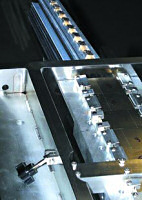
Applications that exploit diamagnetic properties for practical levitation require the integration of permanent magnets in a hybrid system. Strong permanent magnets provide the lift capacity to balance the forces of gravity. Diamagnetic material used with selectively positioned permanent magnets provides the stability to keep the levitation balanced within reasonable limits. SRI International recently developed a hybrid levitation system based on permanent magnets for lift and on diamagnetism for the necessary control stability (patent pending). SRI has actively studied this phenomenon and has developed mechanisms to harness its power in useful applications. These efforts have in turn led to several other patents and inventions. For example, SRI's hybrid levitation system has been used to provide a clean-room transport system for a major manufacturer of magnetic media storage systems. This application has passively levitated more than 16 kg of payload, setting a world record.
In SRI's system, many powerful neodymium-iron-boron bias magnets are mounted on a rigid support structure above a movable transport conveyance. The rigid support structure is stationary. Lift magnets are mounted to the movable transport conveyance (see Figure 7). The bias and lift magnets provide the attractive force necessary to counteract the force of gravity. Fixed magnet arrays are mounted to the same support structure as the bias magnets and straddle the diamagnetic bearing plates that are mounted to the transport conveyance. The diamagnetic bearing plates provide a fraction of the lift through their repulsive force relative to the fixed magnet array, and also provide sufficient repulsive force to counteract the attractive force of the bias and lift magnets. Stop rollers prevent accidental interference between the bearing plates and the fixed magnet array. The clearances between bearing plates and magnet array are small, on the order of 1 mm.
|
Providing that lift forces can be balanced correctly, how can lateral stability be achieved? We can do so by placing the lift magnet at a strategic location in the bias magnetic field. (We determine the location by computer modeling the magnetic field, as shown in Figure 8). At this location, magnetic lines of force hold the lift magnets and transport conveyance in a neutral position under the bias magnets.
Eddy currents also are used to provide stability or opposition to motion in one direction. An aluminum plate mounted on the transport conveyance provides eddy current damping and additional lateral support. When an electrically conductive material (aluminum in this case) is moved in a magnetic field, an electric current is generated. (This is the basic principle of the electric generator; copper conductors moving in a magnetic field generate an electric current that in turn generates its own magnetic field.) The dynamically introduced magnetic field repels the magnetic field of the fixed magnetic array and helps with lateral support. Eddy currents can also provide braking forces (see Figure 9).
 Figure 9. When a piece of aluminum is pushed through the magnetic field perpendicular to the magnetic lines of force, eddy currents within the metal produce an opposing force. In this case, there is a slight braking effect when the plate is pushed in the X direction. If it is pushed in the Y direction, parallel to the magnetic lines of force, no eddy currents or resistance to motion will be encountered. |
The above example was a linear application; we have not yet discussed the possibility of rotating an object around an axis. An impeller with a lift magnet mounted in the center can be levitated between two pieces of diamagnetic material (see Figure 10). Here, the bias magnet is mounted above the impeller to provide lift for the weight of the impeller and the lift magnet. The axis of rotation is defined by the magnetic field. This impeller would be useful in a gas flow control or sensor application and could be mounted in an enclosure that is welded shut, eliminating seals and possible contamination. Particle generation would be eliminated because the impeller rotates in a magnetic field. The gas flow sensor or controller would never need maintenance or adjustment during the life of the unit. SRI has successfully demonstrated a levitated flowmeter with a turndown ratio of 1000:1, a frictionless micromotor operating at 21,000 rpm, and a seismic sensor sensitive down to a few hertz. The possibilities for hybrid diamagnetic levitation are endless.
|
Hybrid levitation systems based on permanent magnets and diamagnetics have their limitations. Weight and balance must be considered early in the design stage of such a system. Although hybrid systems are inexpensive and free of power supplies, control systems, sensors, and other complications of the more sophisticated active systems, they are less stiff than the active systems. In other words, small forces can more easily move them from their designated locations. Their basic design must be tailored to the application. Since no controls are built into the system, the magnetic design and operating specifications must be clear and fully understood.
Diamagnetic levitation is not a panacea for problems with bearing applications. It may, however, find new applications in a wide variety of equipment.
U.S. Patent #5,396,136, Magnetic Field Levitation, is held by Ronald E. Pelrine.
For Further Reading
Readers can find more information on diamagnetism, diamagnetic levitation, and their applications at the following Web sites:
- Martin Simon's Home Page
- The Frog That Learned to Fly
- The Real Levitation
- Physics Demonstrations - Magnetism