

Storage facilities, especially those that maintain their contents at a controlled temperature and humidity, require constant and reliable monitoring. Temperature-controlled storage units are used in a variety of environments including hotels, restaurants, hospitals, pharmacies, warehouses, and transporters. Their monitoring mechanisms help verify acceptable temperature and humidity conditions, reduce costs by preventing overheating or overcooling, avoid losses due to freezer failures, improve quality standards, avoid wastage, and even provide historical temperature reports for insurance. Monitors also help in planning operations and maintenance, for instance, by logging the number of times that doors open or close.
In this article, we describe the design of a sensor unit for storage monitoring, with emphasis on providing for universal connectivity through the existing networking infrastructure.
Figure 1 shows the components of the desired system. The sensor unit may be powered from the same source as the storage unit, or it may be battery powered, enabling more flexible installation and setup. In the following sections, we discuss the general design of the sensor unit, and its implementation using a SenSiFi wireless sensor networking module from Redpine Signals Inc.
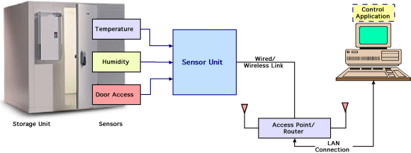 Figure 1. The sensors at the storage unit are controlled by a sensor unit that is connected to a controller via the enterprise network |
Choosing Connectivity
Sensor networks have traditionally used a variety of network protocols. Cabling costs and difficulty in deployment, or redeployment, have resulted in the increasing adoption of wireless as the chosen physical medium of connectivity, with IEEE 802.15.4 ZigBee and Bluetooth as prominent examples of popular wireless protocols. However, there are significant benefits—easy remote monitoring and control and scalability—to having sensors on an IP-based network, which would already be present in most enterprises. One connectivity choice is the 802.11 wireless LAN (WLAN) protocol. Apart from seamlessly connecting to the enterprise network, WLAN also stands out among other wireless standards because of its ability to scale up and cater to increasing densities of wireless nodes. Also, the planning of an organization-wide network—involving decisions on frequency reuse, coverage of cells, and security settings, among others—would have already been done, paving the way for quick and flexible installation and commissioning of equipment and devices. Among 802.11 WLAN variants, the emerging 802.11n standard is preferred due to its increased range and throughput and the provision of enhanced network capacity. The SenSiFi module provides single-stream 802.11n connectivity, while remaining compatible with legacy WLAN networks.
The Sensor Networking Module
The design of the sensor system becomes easier by using an integrated sensor module that offers a few essential features for control and connectivity, as described below.
802.11n wireless communication. The desired core connectivity function is provided by an integrated 802.11n wireless section that includes a baseband processor, MAC, analog front end, an RF transceiver and power amplifier, a frequency reference, and optionally an antenna. A characterized and, if necessary, calibrated RF section provides uniform performance—consistent across all nodes—and reduces the validation requirements for the completed system. Most of the WLAN protocol tasks are carried out in software, and the burnt-in embedded firmware takes care of the standards-compliant WLAN connectivity. The software handling the sensor configuration and control, and the packaging of the data collected can therefore be developed independently. The SenSiFi module (Figure 2) provides this facility, with users entering only the network configuration information.
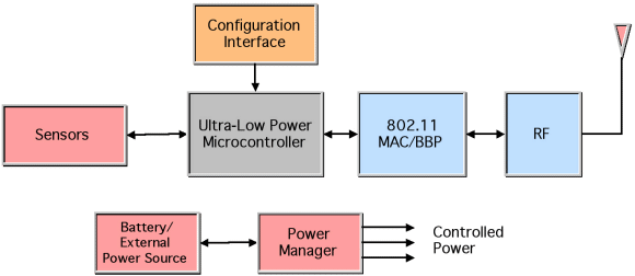 Figure 2. The SenSiFi module contains a wireless LAN section, a sensor interface section, and power management circuitry, with a low power microcontroller providing control and configuration capability |
Ultra-low-power microcontroller. Sensors provide raw data that need to be processed in some way. They also need to be controlled and configured as required by the application; for example, in this case, by setting the frequency of measurement or the frequency of reporting, setting the duration of the warm-up period prior to measurement after powering on, and other parameters. An Atmel ultra-low-power microcontroller within the SenSiFi module has a multichannel ADC and several peripheral interfaces to connect to a variety of sensors.
When the sensor system operates off a battery, the microcontroller is used to control the system's power state, dropping the system into an ultra-low-power sleep mode between measurements. The microcontroller is also used to process and package the sensor data for transmission over the network. In this case, we use the SenSiFi module's embedded operating system that supports standard networking protocols such as IPv4, IPv6, TCP, and UDP. The communication is two-way; sensor data are sent out and system configuration information is sent back from a controller elsewhere on the network.
Power management. The sensor system works off a single power source, either line power or from a battery. Because a battery may produce variable voltages, depending upon its charge state, the sensor module should generate the various voltage levels required by its internal components, as well as for the sensors attached to it. In the SenSiFi module, this is provided by an internal power management subsystem comprising voltage converters, configurable regulators, and switches. The power management functions also include controlling power to function blocks that are placed into standby or power-down modes based on the system's operational state.
Sensor Interface Design
The storage monitor application addressed here uses three sensors: temperature, humidity, and door actions. Of these, temperature and humidity are both commonly available using a single sensor, e.g., the Sensiron SHT-75. The sensor's I2C interface can be connected to the SenSiFi module's I2C interface. The door opening or closing may be monitored using a contact or infrared sensor connected to one of the digital general-purpose I/O (GPIO) lines of the module. This signal is also used as an interrupt to the microcontroller, bringing it out of its sleep state to raise an alarm or to record the activity to provide a history of door opening and closing events, and related duration information.
Data Processing
The microcontroller's main tasks are to control the sensors and process their data. A state machine in the application program running on the microcontroller triggers the temperature and humidity sensor and then collects the sensor data. It also responds to changes in state experienced by the door sensor.
The data are put in a format that can be decoded by the software application executed on the controller or server. This is a proprietary format and contains details such as the type of data being transmitted, the length of the data, the raw sensor data, an optional checksum, and a packet sequence number. This is then encapsulated with an IP header using the uIP stack residing in the SenSiFi module's microcontroller. The uIP stack works in both IPv6 and IPv4 networks.
The Ethernet IP packet thus formed is passed to the WLAN stack which then forms a WLAN packet and transmits the packet over the air where it is routed to the server by the Access Point (AP)/router that converts it back into an Ethernet packet. The server decodes the data and displays the sensor information (Figure 3). A custom server application gathers the sensor data and presents it as needed, e.g., as a graph of temperature over time, as illustrated in Figure 4.
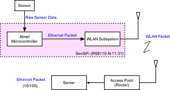 Figure 3. Packet flow from sensor to server |
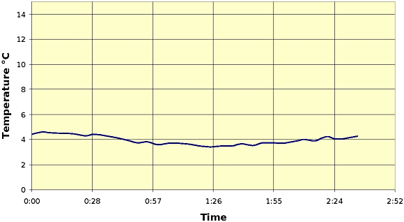 Figure 4. A plot of temperature over time created in a sample server application |
IP Protocols
In the IP layer, the user may choose between two protocols: Transmission Control Protocol (TCP) and User Datagram Protocol (UDP). The choice between these two protocols is governed by the following factors:
- importance of data integrity and order
- power consumption (battery life)
TCP is a flow-control-based protocol that ensures that the data transmitted by a source is received at the destination without fail, unless the connection is terminated. The flow-control mechanism also ensures that data are received in the correct order by using multiple packet exchanges (data and acknowledgement) between the source and destination. This, therefore, would be the ideal method for a sensor network that needs to ensure that all sensor data are received, analyzed, and acted on without fail. However, this also results in the module being in "ON" mode for a longer time, thus resulting in higher energy consumption per transmission cycle. Because the RF transceiver is the most power-hungry component of a wireless system, even a small increase in the time that the transceiver is kept "ON" significantly affects the overall lifetime. The challenge in improving the battery life of nodes in such networks, therefore, lies in optimal and intelligent control of the RF transceiver and other hardware components so as to minimize 'ON' time while assuring the required data transfer performance.
UDP, on the other hand, does not use retry mechanisms that ensure that the data are received by the destination and so does not put too great a load on the network. For this reason, UDP is usually used to transfer streaming data that require low latency and high throughput and is also used for purposes where the intermittent loss of data does not affect the end goal of the application. The power consumption in such a network would be much lower for each transmission cycle. Of course, TCP can be used to achieve the same battery lifetime possible with UDP by altering the frequency at which sensor data are transmitted, since the longer the time that the module is idle, the longer the battery lifetime.
Module Configuration and Setup
The module configuration and setup includes configuring parameters related to WLAN, wakeup intervals, destination IP addresses, transmission rate, and power level. Figure 5 illustrates the configuration utility GUI for the SenSiFi module's evaluation kit.
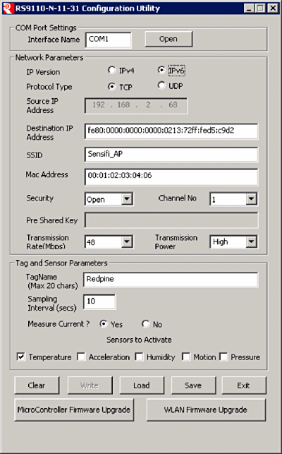 Figure 5. The SenSiFi Module's software package includes a configuration GUI through which WLAN parameters as well as sensor parameters are set |
The storage monitoring application described here would use the parameters shown in Figure 6 during its configuration.
Figure 6. Configuration parameters
| Interface | The PC's COM port used |
| IP Version | IPv4 (and may be IPv6 based on support in the network infrastructure) |
| Protocol Type | UDP |
| Source IP Address | With the use of DHCP, no specific IP address need be provided |
| Destination IP Address | The IP address of the controller/Web Server to which the module transmits the data. |
| SSID | SSID of the wireless access point to which the module will connect |
| Security | The type of WLAN security used by the designated Access Point |
| Pre-shared Key | The security key that is used for connecting to the AP |
| Channel | An optional WLAN channel number to restrict the module to operating in a particular channel, matching the AP's channel of operation |
| Transmission Rate | The data rate that the module uses to transmit the packets on air. The choice of rate largely depends on the distance between the sensor and the AP, and may be left as 'Automatic' if conditions are expected to vary. The higher the data rate, the lower the overall energy consumed during operation |
| Transmission Power | This is a choice of high, medium, or low power. By default, this is set to high power and would be the appropriate choice for our storage monitoring application |
| Tag Name | A suitable name for the sensor node |
| Sampling Interval | The time in seconds between successive sensor data transmissions; a value between 10 s and 30 s would be suitable for this application |
Energy Management
If the sensor unit is running off a battery, the life of the battery can be extended by various methods. The most important from a designer's perspective would be to devise an intelligent way to switch the various components on and off. The SenSiFi system achieves a battery life of 3 years working in IPv6 (UDP) mode while transmitting data from a temperature sensor every 2 minutes. The sample application code that achieves this minimizes power consumption at various levels by:
- Switching off the WLAN subsystem when not required
- Dynamically changing the power modes of the Atmel microcontroller during the time that it is active
- Scheduling events in parallel to reduce the time that it is in active mode. This technique is used both in the microcontroller code as well as in the firmware of the module
- Working at different clock frequencies at different stages to ensure that an optimal balance is achieved between power and active time.
A typical current vs. time graph appears in Figure 7 for a sensor node during its active period. During the idle period between transfers, the consumption of power is so low that it does not appear in the graph.
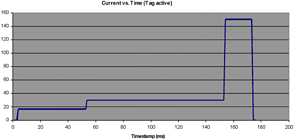 Figure 7. The sensor unit's power profile shown as a graph of current vs. time |
Conclusion
In this design, we have implemented a sensor unit to monitor the temperature and humidity conditions of a cold storage unit, as well as to log the storage unit access events. We have chosen appropriate physical sensors and interfaced them to the SenSiFi sensor networking module. All the operational configuration information is programmed into the module. In this case, with no special requirement on data conditioning, no additional software is required to be written into the integrated microcontroller. The required data are made available over an existing WLAN network to be collected and analyzed by a controller or server at a local or remote location, fulfilling the needs of a universally connected, versatile, and effective storage monitoring system.
ABOUT THE AUTHORS
N. Venkatesh, Vice President of Advanced Technologies ([email protected]) and Rohan Joginpalli, Product Manager, ([email protected]) can be reached at Redpine Signals Inc., San Jose, CA; 408-826-8038.