

Thermopile temperature or temp sensors offer the advantage of non-contact temperature measurement, making them more and more popular over the standard contact-based temp sensors. Thermopile sensors use infrared (IR) radiation versus conduction for heat transfer, which provides unique solutions that allow for new levels of performance and reliability in many constrained applications.
Engineers working on the thermal management of electronic equipment have long enjoyed the simplicity and convenience of the digital temp sensing ICs. The new integrated thermopile sensor ICs on the market provide the temperature results in the same convenient digital format. The continuous reduction in their power, size, and cost creates opportunities with consumer devices, medical instruments, office equipment and home appliances.
The most active adoption of small thermopile IR sensors is in portable devices such as notebooks, tablets, and smartphones. Measuring the case temperature provides key input in optimizing performance. Keeping the processor running at peak power, while maintaining the case temperature comfortable for the user, is the main design constraint in the pursuit of more processing power in smaller form factors.
Using contact temp sensors on the board to correlate its temperature to the case temperature yields very inaccurate results. Plus, it doesn't account for any changes of the ambient conditions, i.e., using your tablet outside in a sunny day or in a hockey rink. A contact temp sensor glued to the case, with wires connecting it to the board, can solve that problem. But it's a nightmare for manufacturing as it involves manual assembly and has poor reliability.
A thermopile IR temp sensor can be mounted to a printed circuit board (PCB) with standard automated processes. It measures both the board and case temperature, which allows for true feedback control and optimization.
Another attractive application for IR temp sensors is temperature monitoring and control of moving objects such as heater rolls in laser printers. In these cases, using contact-based temp sensors comes with many draw-backs. For example, the point of contact wears out from friction during movement. This gets exacerbated by applying normal force on the sensor to achieve good thermal contact. Also, the contact location might not be at the point of interest. This creates a time-constant for heat transfer between the two locations and could compromise the control system's efficiency. An IR temp sensor can eliminate all of these constraints.
There are a few peculiarities about thermopile IR temperature sensors that must be addressed in order to take full advantage of this technology. A thermopile IR sensor has a number of thermocouples connected in series that have their "hot" junctions attached to a thin IR absorber, typically on a micro-machined membrane on a silicon chip (see figs. 1, 2, and 3).
The exchange of IR radiation between the absorber and the object in front of it makes the temperature of the absorber rise or fall, depending on the temperature difference between it and the object. This process is governed by Plank's law of blackbody radiation (fig. 3), and Stefan-Boltzmann law of radiative heat transfer (fig.2). The small mass of the absorber provides the fast thermal equilibrium with the object. The small thickness provides a thermal insulation from the bulk material of the chip, resulting in the temperature gradient between the absorber's middle and the bulk of the chip.
Fig. 1: Thermocouple vs. thermopile
Fig. 2: Typical thermopile IR sensor diagram
Fig. 3: Plank's law of spectral radiance at temperatures from –40°C to 125°C
The thermocouples' "cold" junctions are located in the bulk. A built-in temp sensor measures the bulk temperature, which functions as a reference point for the calculations. The voltage created on a single thermocouple is proportional to the temperature difference between the two junctions. The coefficient of proportionality is called the Seebeck coefficient: coming from the Seebeck effect that describes the thermocouple principle of operation.
The thermopile's total voltage is equal to the sum of the voltages across all the individual thermocouples. In the case of identical thermocouples in series, it's the number of thermocouples multiplied by the voltage across one of them. The object temperature is calculated from the measurements of the sensor die temperature, TS, and the output voltage of the thermopile. The simplified formula for the thermopile voltage is derived from Stefan-Boltzmann's law and the Seebeck effect via Equation 1:
VTP = A•(TO4 – TS4)
In Equation 1, VTP is the thermopile voltage, TO is the object temperature, and TS is the sensor temperature. In the case of A = RTH•N•S•ε•σ•F; RTH = thermal resistance, N = number of thermocouples, S = Seebeck coefficient, ε = net emissivity, σ = Stefan's constant, and F = Field of view (FOV).
To properly measure the object's temperature, the object must completely fill the sensor's field of view (FOV). This ensures that the IR radiation affecting the thermopile is coming only from the object of interest and not its background. The emissivity of a material represents its ability to emit IR radiation, compared to an ideal blackbody with ε=1. Human skin, glass, wood, and oil-based paint all have very good emissivity that is greater than 0.9, while polished metals and gypsum have emissivity of less than 0.1.
Lower emissivity leads to a lower IR signal from the object with higher object reflectivity, since the sum of reflectance, transmittance and absorbance/emissivity totals 1. This causes the sensor to measure the reflected objects' temperature rather than the object of interest. Therefore, an object's high emissivity is desired for proper IR temperature measurements. Applying black tape or paint to the surface of a low-emissivity object fixes this problem.
The combined coefficient A is subject to calibration that, if done on the final system, takes care of emissivity and FOV uncertainties. VTP and TS are measured by the sensor. A stricter consideration takes the absorber versus sensor bulk temperature where the built-in temp sensor is located. Typically, the difference is in the mK range, so this approximation is valid for most practical cases. The object temperature is derivable using Equation 2:
TO = (TS4 + VTP /A)1/4
This formula is valid for a sensor in a well-insulated package, typically a metal can, with inert gas or even vacuum inside, which causes the predominant heat transfer to happen through IR radiation. In the smallest versions of the IR sensors, such as the TMP006 that is in a wafer-level chip-scale package (WCSP), the sensor and the absorber membrane are directly exposed to ambient environment. This makes the sensor more sensitive to conduction and convection, which are the other two heat transfer mechanisms, versus radiative heat transfer. The resulting effect is the sensor's thermopile voltage drift as a function of the sensor die temperature. A total of three coefficients are used to compensate for this voltage drift, as per Equation 3:
VOS = b0 + b1(TS – TREF) + b2(TS – TREF)2
In Equation 3 above, VOS is the offset voltage when TO and TS are equal (for example, the object and the sensor have the same temperature), and TREF is room temperature (+25°C or +298°K). This offset is calculated and subtracted from the thermopile voltage at every measurement point, and the resulting voltage for the object temperature calculation is given by Equation 4:
f{VO} = (VTP – VOS) + c2(VTP – VOS)2
The coefficient c2 accounts for the deviation from the ideal Stefan-Boltzmann model due to the limited spectral range of real sensors and provides a second order compensation. The formula for the object temperature calculation then becomes as in Equation 5:
TO = (TS4 + f{VO}/A)1/4
Large transients on the sensor temperature also affect measurement accuracy. Insulating the membrane creates a thermal lag between its temperature and the bulk temperature in a fast change of the PCB or ambient temperature. The "hot" junction is isolated from the rest of the sensor by the sensor's thermal resistivity.
When the sensor's "cold" junction temperature is changed through heat conduction from the outside, the hot junction follows, but is delayed by a time constant. This effect can be modeled with a first order RC filter that delays the hot junction relative to the sensor substrate temperature (see fig. 4).
Fig. 4: Transient temperature effect
A temperature gradient is created on the thermopile during transients that is proportional to the slope of the transient itself. This gradient generates an error voltage through the Seebeck effect, calculated with Equation 6.
VERR = S•RTH•CTH•(– dTS/dt) = – α•(dTS/dt), where α = S•RTH•CTH
This error voltage can be calculated by knowing or calibrating α and keeping track of the slope of the sensor temperature at any point. The transient correction is done by subtracting the error voltage from the f{VO} term in the object temperature calculation Equation 5, or from VTP in Equation 2.
Lastly, using filter and lens materials greatly enhances the performance of the IR sensors. Interestingly, glass being transparent in the visible spectrum is completely opaque in the IR domain. This is why measuring the temperature with an IR sensor through a glass window is not possible. On the other hand, plain silicon is completely opaque to visible light, but it's transparent to wavelengths longer than 2 µm where most spectral emission occurs for temperatures below 500 K (~200°C or ~450°F). This makes silicon a popular material for filtering the visible and UV spectrum from affecting the sensor. With modern micro-machining technologies, the silicon surface also can be shaped as a lens in order to concentrate more IR radiation onto the sensor or limit the FOV. This can increase the sensor's sensitivity, or the distance that the sensor can measure a fixed-size object. This concept is illustrated in fig. 5.
Fig. 5: Silicon lens/filter implementation
A successful implementation of a temp sensor such as the TMP006 in a laptop case temperature measurement is illustrated in figs. 6 and 7. The IR sensor is mounted on a small coupon board glued to the main board with epoxy. A reference high-accuracy contact temp sensor is attached to the case, and the case is spray-painted black to ensure high emissivity. The results in Figure 7 show the measurements of the IR sensor compared to the local sensor, with the error not exceeding 2°C, during a stress test that lasted more than 30 minutes and rose the board temperature to over 50°C.
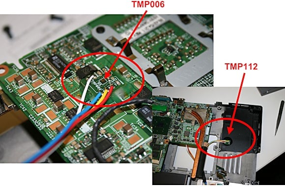
Fig. 6: Thermopile IR implementation in a laptop case temperature measurement
Fig. 7: Results from the laptop case temperature measurement
Conclusion
In summary, thermopile IR temp sensors provide the best combination of small-size, low-power and low-cost solutions for non-contact temperature measurements. Even though they are not as trivial to implement as the conventional contact-based temp sensor, the benefits greatly outweigh the additional considerations that engineers need to address for their proper operation. Furthermore, the application engineering teams of all major suppliers are eager to assist in this process and shift the paradigm of thermal management in many of the devices we use today in our everyday life.
References
Datasheet: http://www.ti.com/tmp006-ca.
Learn more about temp sensors at http://www.ti.com/sensors-ca
About the Authors
Vasco Polyzoev is a systems engineer with TI's Sensing Products group. He received his PhD degree from University of Arizona. For questions about this article, you can contact Vasco at [email protected].
Habib Karaki is an analog design engineer with TI's Sensing Products group. He received his electrical engineering degree from the American University of Beirut, Lebanon, and his master's from Arizona State University.