

Most modern digital oscilloscopes sport decode software for many well-known serial-data protocols, which include I2C, SPI, CAN, USB, and Ethernet. Meanwhile, some emerging and/or lesser-known protocols, including some specifically aimed at sensor-to-controller applications, find themselves out in the cold with respect to decode software.
In many cases, the basic Manchester and NRZ line-encoding schemes form the basis for these emerging serial-data protocols. For example, the Peripheral Sensor Interface 5 (PSI5) protocol, a two-wire digital interface used to connect peripheral sensors to ECUs, is finding favor in automotive applications. PSI5 has its basis in the Manchester line-encoding scheme.
This article will show how to use a configurable protocol decoder available for many Teledyne LeCroy oscilloscopes to decode signals using the Manchester and NRZ encoding schemes. Here, we will use the example of decoding a PSI5 signal with the Manchester decoder. Note also that many design teams create custom, proprietary protocols based on Manchester and NRZ; the configurable encoder adapts to decode any such schemes.
About the PSI5 Physical and Data Link Layers
PSI5 uses two wires for both the power supply to the sensors and for data transmission. The ECU provides a pre-regulated voltage to the sensor. Data transmission from the sensor to the ECU occurs by current modulation on the power supply lines. The ECU and the input impedances of the sensors damp current oscillations.
Data transmission is accomplished using Manchester encoding. A logic "0" is represented by a rising slope and a logic "1" by a falling slope of the current in the middle of a given bit.
At the data link layer, each PSI5 data frame—separated by a gap of more than one bit—consists of:
- two start bits always coded as "0"
- one parity bit with even parity or three CRC bits
- a payload data region
Embarking on a Decode
In this case, the signal being examined is a 125-kb/s PSI5 signal with a 13-bit data frame consisting of two start bits, 10 data bits, and one parity bit. This signal is current modulated, which typically indicates sensor-to-ECU communication. Conversely, ECU-to-sensor communication requires voltage modulation on the supply lines.
On a Teledyne LeCroy HDO oscilloscope, serial decode functions are accessed through the Analysis drop-down menu. From there, a few menu selections set up the instrument for Manchester decoding.
The Three Tabs: Basic, Decode, and Levels
The Decode Setup dialog presents the user with three "sub-tabs" labeled Basic, Decode, and Levels (see fig. 1). The Basic tab provides all of the fundamental controls for proper bit-level decoding. Input the appropriate Bit Rate using the Bit Rate parameter in the Physical Layer portion of the Basic tab. The PSI5 specification dictates two fixed data-transmission rates of 125 kb/s or 189 kb/s. The signal used for this example is at a bit rate of 125 kb/s.
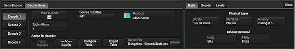 Fig. 1: The Decode Setup dialog with the Basic, Decode, and Levels tabs shown at right. Click image to enlarge. |
The Timeout Definition for the gap between bursts comprises two parameters, Units and # Bits. The former can be set to either Bits or Seconds. If Bits is chosen, the range is from 1 to 100. If Seconds is used, the range is from 1 to 99.99 µs. As noted above, the gap between frames for PSI5 must exceed the duration of one bit. For this example, it has been set at 6 bits.
The Idle State, which complements the Timeout Definition parameters, may be set to either IdleHigh, IdleLow, or Don't Care. Setting the Idle State helps precisely define the separation gap between data bursts. For sensor-to-ECU communication in PSI5, the idle state between data frames corresponds to the quiescent current consumption of the sensor. Thus, the Idle State is set to IdleLow.
The Polarity may be set to either Falling = 0 or Falling = 1. This determines whether an edge falling through the threshold level is decoded as a logical 0 or a logical 1, respectively. The PSI5 specification dictates that an edge falling through the threshold level equates to a logical 1. Thus, for this example, Polarity is set at Falling = 1.
To ensure that the bit-level decode is correct, zoom in on a portion of the decoded signal by drawing a rectangle around it on the screen. This opens a zoomed view of that portion as shown in the lower portion of the screen capture in figure 2 below.
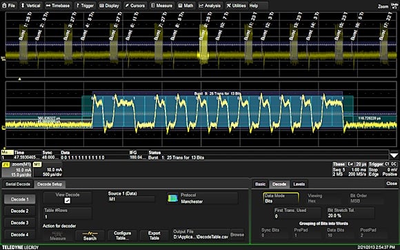 Fig. 2: Verifying correct bit-level decode with a zoomed view. Click image to enlarge. |
Note that in the zoomed view, Z1, each binary 1 is represented by a positive half-bit period pulse followed by a negative half-bit period pulse. Similarly, a binary 0 is represented by a negative half-bit period pulse followed by a positive half-bit period pulse. This type of signaling is also called split–phase encoding. In this case, Polarity is set to physical Falling = 1.
The Decode Tab
The Decode tab is where decode at the word level is set up (see fig. 3).
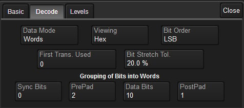
Fig. 3: The Decode tab in the Decode Setup dialog.
The First Transition Used (FTU) parameter accounts for items that may precede the actual data payload, such as a preamble or synchronization sequence. The default setting for FTU is zero; it can range in increments of one to a maximum of 400.
The Bit Stretch Tolerance parameter comes into play when transitions often occur at mid-bit. Due to hardware or signal-propagation issues, these mid-bits may not be equidistant. Adjust this parameter to better decode jittery signals. After setting the Bit Rate on the Basic tab, the Bit Stretch Tolerance may require adjustment from its default setting of 20% to achieve stable decoding.
At the bottom of the Decode tab is a number of parameters for Grouping of Bits into Words. Figure 4 shows the PSI5 signal grouped into words with a zoomed view of a single burst. In this case, the decoded data is 0x01, a status message sent by the sensor to its associated ECU.
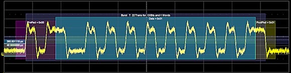 Fig. 4: A Manchester signal shown decoded in Word Mode. Click image to enlarge. |
Bits may be grouped into Sync Bits, PrePad, Data Bits, and PostPad. Again, at the data link layer, each PSI5 data frame consists of two start bits, one parity, or three CRC bits, and a payload data region.
PrePad bits comprise messages, frame control bits, or status bits, all of which are optional in the PSI5 specification. The trace shown has only two start bits in the PrePad section. In Figure 4, they are the portions of the bit stream seen with a purple overlay.
The Manchester decoder can parse from one to 32 Data bits. The PSI5 specification provides from 10 to 24 data bits in Data Region A, and up to 12 more bits in an optional Data Region B. The trace seen here has 10 data bits, which are marked with a blue overlay.
PostPad bits serve to group information following the data bits. The Manchester decoder allows from zero to 32 PostPad bits representing a CRC, a checksum, or other protocol constructs. PSI5 specifies either a single parity bit or three CRC bits. In the trace used for this document, there is one parity bit. PostPad bits carry a yellow overlay.
The Level Tab
The last of the three tabs in the Decode Setup dialog box is the Level tab. Levels can be set using either percentage or absolute voltage values. The Level setting itself determines the threshold that transitions must cross to count as transitions. The default value is 50% or 1.5 V for percentage and absolute level types, respectively.
Hysteresis settings account for noisy signals with spikes that may create false transitions if they cross the Level threshold. It appears as a blue-shaded band centered vertically on the Level setting. The default Hysteresis value is 15%, but it may range from zero to 50%.
Conclusion
Teledyne LeCroy's configurable Manchester decoder reveals the intricacies of PSI5 signals as well as others encoded with the Manchester scheme. Armed with a bit of foreknowledge of the signal under test, users may exploit the decoder's nearly unlimited flexibility with respect to signal parameters to cleanly decode and display signals and extract data relative to their physical characteristics.
About the Author
David Maliniak is Technical Marketing Communications Specialist at Teledyne LeCroy. He blogs, creates support documentation, and writes the occasional technical article. Before joining Teledyne LeCroy in 2012, David was Test and Measurement/EDA Technology Editor at Electronic Design Magazine.