Ultrasonic sensors are commonly used for a wide variety of noncontact presence, proximity, or distance measuring applications. These devices typically transmit a short burst of ultrasonic sound toward a target, which reflects the sound back to the sensor. The system then measures the time for the echo to return to the sensor and computes the distance to the target using the speed of sound in the medium [1,2,3].
The wide variety of sensors currently on the market differ from one another in their mounting configurations, environmental sealing, and electronic features. Acoustically, they operate at different frequencies and have different radiation patterns. It is usually not difficult to select a sensor that best meets the environmental and mechanical requirements for a particular application, or to evaluate the electronic features available with different models. Still, many users may not be aware of the acoustic subtleties that can have major effects on ultrasonic sensor operation and the measurements being made with them.
The overall intent of this article is to help the user select an ultrasonic sensor with the best acoustical properties, such as frequency and beam pattern, for a particular application, and how to obtain an optimum measurement from the sensor. The first step in this process is to gain a better understanding of how variations in the acoustical parameters of both the environment and the target affect the operation of the sensor. Specifically, the following variables will be discussed:
• Variation in the speed of sound as a function of both temperature and the composition of the transmission medium, usually air, and how these variations affect sensor measurement accuracy and resolution
• Variation in the wavelength of sound as a function of both sound speed and frequency, and how this affects the resolution, accuracy, minimum target size, and the minimum and maximum target distances of an ultrasonic sensor
• Variation in the attenuation of sound as a function of both frequency and humidity, and how this affects the maximum target distance for an ultrasonic sensor in air
• Variation of the amplitude of background noise as a function of frequency, and how this affects the maximum target distance and minimum target size for an ultrasonic sensor
• Variation in the sound radiation pattern (beam angle) of both the ultrasonic transducer and the complete sensor system, and how this affects the maximum target distance and helps eliminate extraneous targets
• Variation in the amplitude of the return echo as a function of the target distance, geometry, surface, and size, and how this affects the maximum target distance attainable with an ultrasonic sensor
Fundamental Ultrasonic Properties
Ultrasonic sound is a vibration at a frequency above the range of human hearing, usually >20 kHz. The microphones and loudspeakers used to receive and transmit the ultrasonic sound are called transducers. Most ultrasonic sensors use a single transducer to both transmit the sound pulse and receive the reflected echo, typically operating at frequencies between 40 kHz and 250 kHz. A variety of different types of transducers are used in these systems [4]. The following sections provide an overview of how the sound pulse is affected by some of the fundamental ultrasonic properties of the medium in which the sound travels.
Speed of Sound in Air As a Function of Temperature
In an echo ranging system, the elapsed time between the emission of the ultrasonic pulse and its return to the receiver is measured. The range distance to the target is then computed using the speed of sound in the transmission medium, which is usually air. The accuracy of the target distance measurement is directly proportional to the accuracy of the speed of sound used in the calculation. The actual speed of sound is a function of both the composition and temperature of the medium through which the sound travels (see Figure 1).
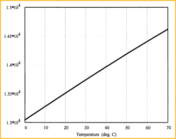 Figure 1. The speed of sound is plotted as a function of the temperature. At room temperature, sound travels at ~13,500 ips. Figure 1. The speed of sound is plotted as a function of the temperature. At room temperature, sound travels at ~13,500 ips. |
The speed of sound in air varies as a function of temperature by the relationship [5]:
| | (1) |
where:
| c(T) | = speed of sound in air as a function of temperature in inches per second |
| T | = temperature of the air in °C |
The speed of sound in different gaseous media is a function of the bulk modulus of the gas, and is affected by both the chemical composition and temperature. Table 1 gives the speed of sound for various gases at 0°C [6].
| TABLE 1 |
| Speed of Sound for Various Gases |
| Gas | Speed, in./s at 10°C |
| Helium | 38,184 |
| Hydrogen | 49,980 |
| Illuminating Gas | 19,308 |
| Methane | 17,004 |
| Neon | 17,124 |
| Nitric Oxide | 12,792 |
| Nitrogen | 13,152 |
| Nitrous Oxide | 10,308 |
| Oxygen | 12,492 |
| Steam (100°C) | 15,876 |
| Gas | Speed, in./s at 10°C |
| Air | 13,044 |
| Ammonia | 16,332 |
| Argon | 11,886 |
| Carbon Dioxide | 10,152 (low frequency) 10,572 (high frequency) |
| Carbon Disulfide | 7,272 |
| Carbon Monoxide | 13,272 |
| Chlorine | 8,088 |
| Ethylene | 12,360 |
Wavelength of Sound As a Function of Sound Speed and Frequency
The wavelength of sound changes as a function of both the speed of sound and the frequency, as shown by the expression:
| λ = c/f | (2) |
where:
| λ | = wavelength |
| c | = speed of light |
| f | = frequency |
Figure 2 is a plot of the wavelength of sound as a function of frequency at room temperature in air.
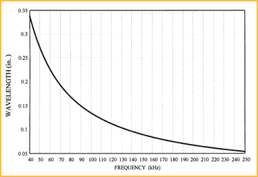 Figure 2. The wavelength of sound in air at room temperature is plotted as a function of frequency. Figure 2. The wavelength of sound in air at room temperature is plotted as a function of frequency. |
Attenuation of Sound As a Function of Frequency and Humidity
As the sound travels, the amplitude of the sound pressure is reduced due to friction losses in the transmission medium. Knowing the value of this absorption loss, or attenuation, is crucial in determining the maximum range of a sensor. The attenuation of sound in air increases with the frequency, and at any given frequency the attenuation varies as a function of humidity. The value of humidity that produces the maximum attenuation is not the same for all frequencies [7]. Above 125 kHz, for example, the maximum attenuation occurs at 100% RH; at 40 kHz, maximum attenuation occurs at 50% RH.
Since an ultrasonic sensor usually is required to operate at all possible humidities, target range calculations should use the largest value of attenuation. A good estimate for the maximum attenuation in air at room temperature over all humidities for frequencies up to 50 kHz is given by:
| α(f) = 0.01 f | (3a) |
where:
| α(f) | = maximum attenuation in dB/ft |
| f | = frequency of sound in kHz |
Between 50 kHz and 300 kHz, the maximum attenuation over all humidities is:
| α(f) = 0.022 f – 0.6 | (3b) |
Figure 3 and Figure 4 illustrate the attenuation of sound as a function of frequency and humidity.
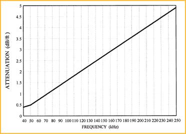 Figure 3. The maximum attenuation of sound in air at room temperature can be plotted as a function of frequency over all humidities for frequencies between 40 kHz and 250 kHz. Figure 3. The maximum attenuation of sound in air at room temperature can be plotted as a function of frequency over all humidities for frequencies between 40 kHz and 250 kHz. |
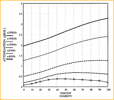 Figure 4. This family of curves shows the variations in the attenuation of sound in air at room temperature as a function of humidity for frequencies between 40 kHz and 200 kHz. Figure 4. This family of curves shows the variations in the attenuation of sound in air at room temperature as a function of humidity for frequencies between 40 kHz and 200 kHz. |
Background Noise
The level of background ultrasonic noise diminishes as the frequency increases. The reason is that less noise at the higher frequencies is produced in the environment, and the noise that is produced is greatly attenuated as it travels through the air.
Effects of Frequency, Distance, and the Transmission
Medium on the Magnitude of Sound Pressure
In an ultrasonic sensor, the transducer produces a short pulse of sound. The magnitude of the sound pressure generated will vary from one type of sensor to another. In acoustics, sound pressures are typically expressed in decibels because of their large dynamic ranges. Sound pressure is usually measured in micropascals (µPa) at a reference distance, R0, from the sensor, usually 12 in. (30 cm). The sound pressure level (SPL) at R0 is then converted to dB referenced to (//) 1µPa as follows:
| SPL(R0) = 20 log(p) | (4) |
where:
| SPL(R0) | = sound pressure level at distance R0 in dB//1µPa |
| p | = sound pressure at distance R0 in µPa |
As the sound travels through the medium, the magnitude of the sound pressure is reduced due to both absorption (attenuation) and spreading loss caused by the expanding surface of the radiating beam as the sound pulse travels from the transducer. The SPL at a distance R from the transducer is given by:
| SPL(R) = SPL(R0) - 20 log (R/R0) - α (f) R | (5) |
where:
| SPL(R) | = sound pressure level at distance R in dB//1µPa |
| SPL(R0) | = sound pressure level at distance R0 in dB//1µPa |
| α(f) | = attenuation coefficient in dB/unit distance at frequency f |
Relative Echo Levels From a Flat Surface for
Different Ultrasonic Frequencies
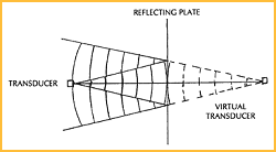 |
Equation (5) can be used to compute the relative effect of varying the sound frequency on echoes produced from a flat reflector at different distances from the sensor. In Figure 6, it is assumed that each sensor produced the same SPL at a range of 1 ft.
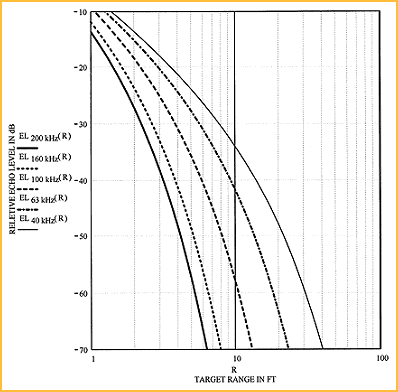 Figure 6. The relative echo levels from a flat reflecting target at varying distances are plotted against range for different frequencies. Figure 6. The relative echo levels from a flat reflecting target at varying distances are plotted against range for different frequencies. |
Therefore, the variations in EL are only a function of the varying attenuations due to the different frequencies of sound. The maximum attenuation for all humidities was used for the value of α for each frequency.
Summary
Part 1 of this article has provided an overview of the some of the fundamental acoustical parameters that affect the operation of an ultrasonic sensor. Part 2 will address the use of these acoustical data to optimize the selection of an ultrasonic sensor for a particular measurement.
References
1. Frank Massa. May 1992. "Ultrasonics in Industry," Fiftieth Anniversary Issue, Proc IRE.
2. Donald P. Massa. Oct. 1987. "An Automatic Ultrasonic Bowling Scoring System," Sensors, Vol. 4, No. 10.
3. Paul A. Shirley. Nov. 1989. "An Introduction to Ultrasonic Sensing," Sensors, Vol. 6, No. 11.
4. Frank Massa. Oct. 1965. "Ultrasonic Transducers for Use in Air," Proc IEEE, Vol. 53, No. 10.
5. Leo L. Beranek. 1972. "Acoustic Properties of Gases," American Institute of Physics Handbook, 3rd Ed. (Section 3d), McGraw-Hill.
6. Handbook of Chemistry and Physics, 45th Ed., 1964.
7. L.B. Evans and Bass. Jan. 1972. "Tables of Absorption and Velocity of Sound in Still Air at 68°F," Wyle Laboratories, Report WR72-2.