
Still, there are transmitter characteristics unique to each technology, such as pressure range, temperature range, zero displacement due to overpressure, long-term thermal drift both at zero and over span, and the ability to measure absolute or gauge pressure. Today, sensor manufacturers are developing broader product portfolios and offering more than one sensor technology.
It is difficult to make a fair judgement about strengths and weakness of pressure transmitter performance characteristics when different technologies are involved. The specifications must be judged with respect to specific application demands.
The table in Figure 1 represents a performance evaluation of the majority of transmitter types on the market today. Note that individual products are available where special measures have eliminated some of the weaknesses of the product's transmitter type.
Figure 1. A performance comparison of the majority of current transmitter types
| Ceramic capacitive | Ceramic thick film | Thin-film | Monolithic piezoresistive semicond. | Bonded piezoresistive semicond. | |
| Pressure range |
0.01–60 bar 0.15–900 psi |
4–60 bar 60–900 psi |
10–2000 bar 150–30,000 psi |
0.1–600 bar 1.5–8700 psi |
5–3000 bar 70–43,500 psi |
| Accuracy | ++ | – | +++ | ++ | + |
|
Operating temperature span |
+ | + | +++ | ++ | ++ |
|
Long-term stability |
++ | + | +++ | ++ | ++ |
| Pressure peak resistance | + | + | ++ | +++ | ++ |
| Over pressure safety | ++ | + | + | +++ | ++ |
| Burst pressure safety | ++ | + | ++ | ++ | ++ |
| Resistance to shock / vibration | ++ | ++ | +++ | +++ | +++ |
| Hermetic tight pressure port (No seals) | – | – | ++ | ++ | +++ |
| Absolute | +++ | + | – | +++ | – |
| Gauge | ++ | ++ | ++ | ++ | ++ |
| Low cost | +++ | +++ | ++ | ++ | ++ |
+++ = very good
++ = good
+ = satisfactory
– = less satisfactory or not applicable
Pressure transmitters used in industrial environments can be divided into families according to functionality and complexity (Figure 2). Often, as functionality and flexibility decline, prices decline and market volume increases.
 Figure 2. Flexibility and complexity as they relate to various markets, applications, and cost. As the width of the triangle increases, so do flexibility, complexity, and usually cost; some relative costs are shown at right |
This article will focus on cartridge-style pressure transmitters used in general industry; heavy-duty off-highway applications; heavy-duty automotive applications; and heating, ventilation, air-conditioning, and refrigeration systems (HVACR).
Operating Conditions and Performance Demands
When selecting a sensor for a particular application it is important to consider the operating conditions to which the sensor will be exposed and the performance required (Figure 3).
 Figure 3. Summary of operating conditions, application requirements, and performance characteristics to consider in your decision-making process |
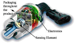 Figure 4. The combination of these elements (sensing element, circuitry, and packaging) must perform to design specifications for the end product, in the environmental conditions where the end product will be used |
- The sensing element that transforms pressure into an electric signal
- Electronic circuitry to condition and amplify the signal
- Packaging, which includes design of the enclosure and mechanical design elements throughout the product
Material Handling Applications. In load sensing for tilt control, for example, the position of the load is often controlled by a hydraulic system. To calculate tilt risk, at least three conditions enter into the evaluation and modeling: pressure on the hydraulic cylinder, boom angle, and load position. In this application there are two demanding conditions under which a pressure transmitter must be able to work: pressure fluctuations caused by pressure peaks, liquid hammering, and cavitation; and temperature and humidity extremes.
With a load on the forklift's forks, rough terrain introduces a great risk of rapid load variation. Abrupt load variations can create pressure peaks, liquid hammering, and in some cases cavitation that shortens equipment life.
Liquid hammering occurs when liquid continues its flow in the pipe after a valve has been closed or a pump shut off. Vacuum builds and the liquid returns as a pressure peak or "liquid hammer" at the sensor diaphragm. Pressure peaks can cause plastic deformation or breakage of the diaphragm.
Cavitation occurs when small and mainly empty cavities ("bubbles") are generated in a fluid and first expand, then rapidly collapse. This happens when pressure falls below the vapor pressure of the fluid (it is almost the same as the effect that occurs during boiling). A thin sealing diaphragm is especially vulnerable to the asymmetric pressures that result from cavitation.
In material handling applications, depending on the sensing technology used, a pressure transmitter's sensor element may be prone to damage from liquid hammering, cavitation, or both. To avoid damage from either, consider using a transmitter with an integral pulse snubber (Figure 5). A pulse snubber is a small, angled orifice built into the pressure inlet of the pressure transmitter to protect against liquid hammering and cavitation. Its angled design ensures that the cavitation bubbles do not reach the sensor element and cause damage.
 |
 |
|
Figure 5. A transmitter without a pulse snubber (A) can experience cavitation bubbles. Using a pulse snubber (B) prevents cavitation
|
|
Often, small forklifts work under conditions where they experience many temperature changes during a workday, moving in and out of buildings or picking up and delivering goods in cold-storage warehouses. These temperature and humidity extremes bring specific risks. Moisture can enter the encapsulated transmitter, exposing the electronics to damage. If this is the case, selection should focus on the transmitter's protective enclosure. If a gauge version is used, make sure that the design for reference to the atmosphere does not subject the transmitter to damage by allowing moisture to enter.
Most transmitters have a thermal error shift affecting both zero point and span. Depending on the manufacturer and the technologies used, the thermal error shift typically varies from 0.1%–0.6% F.S./10°K. Forklifts in cold storage warehouses often operate in an environment where temperature changes from –40°C to 30°C, a span of 70°C. Depending on the time spent in the warehouse, and depending on the transmitter mounting location, such a large temperature change can produce a significant error in the transmitter output signal. (e.g., a 20°C span is equivalent to an error of 1.2%). In this case, the important question is whether the product offers acceptable thermal-shift error data.
Construction and Forestry Equipment. These machines use pressure transmitters on their engines and hydraulic systems. In hydraulic system applications you will often find conditions similar to those described earlier for forklifts. Products used on rough-terrain equipment must be able to work under extremely difficult mechanical and environmental conditions. The equipment is exposed to weather conditions of every kind and to high levels of moisture, dust, shock, and vibration. For these types of applications, focus on the sensor's connectors and sealing.
Engines for Vessels and Power Plants. These applications are often characterized by temperatures up to 125°C and pronounced vibration. Constant high temperatures for extended periods can result in significant output signal drift. Combined with vibration, this presents a severe challenge for the product packaging. Focus on sensor technology with acceptable long-term drift data at higher temperatures. For fuel oil applications, choose a transmitter with an integral pulse snubber to protect against any damage that could be caused by pressure spikes or cavitation.
Water Booster Systems. In this application, transmitters risk exposure to water hammering and cavitation in two ways: Transmitters mounted just after a valve are exposed whenever the valve closes; alternatively, a transmitter placed in a long water line can experience hammering and cavitation whenever flow is stopped. For these types of applications, focus on the sensor element's robustness and look for a transmitter with an integral pulse snubber.
Refrigeration Systems. Some refrigeration systems operate in low pressure ranges of about 1 bar. They are normally closed systems with no reference to the atmosphere. In this case, you need an absolute or, at least, a sealed gauge pressure transmitter. If you use a gauge version, you will see error related to one or both of the following:
- The change in atmospheric pressure (max. ±50 mbar, ±1.48 in. Hg)—If a transmitter's F.S. range is 1 bar, a change of 50 mbar in atmospheric pressure will result in an error equivalent to 5%.
- The change in altitude (–100 mbar/1000 m)—Here, for a 1 bar transmitter, there can be an error equivalent to 10%/1000 m change in altitude. In Denver, a mile above sea level, a transmitter not recalibrated for the altitude would be subject to error of 16%.
The same effect occurs when using an absolute pressure transmitter to measure level in an open tank system.
Be a Methodical Customer
After a thorough technical analysis, it is important to evaluate the company behind each product you are considering. Product quality and delivery should be key determining factors.
In supplier evaluation, follow a methodical course, completing every step.
- Select a few suppliers that you believe are reliable and can deliver the products you need. Find suppliers who are interested in serving the application demand, not simply the specification on a blueprint.
- Audit the company behind the products as to:
- Tools used during product design, such as design failure modes and effect analysis (DFMEA), lean development, and availability of test results
- Tools used in production, such as process failure modes and effect analysis (PFMEA), process capability tracing (Cpk values) both internally and at suppliers, control plans, production scrap level in ppm, level of field complaints in ppm, and corrective action programs
- Support: logistic setup, availability of technical support, and complaint handling
- Test the product in the application. It can be difficult to anticipate all operating conditions. To avoid any surprises when using the pressure transmitters in running production, make functionality and performance tests on the real application.
Total Cost of Ownership
When choosing a product, make sure to specify the application's actual requirements. Select the product by specification. Sometimes "you get what you pay for" applies, but it's also certain that "you will pay for what you ask for." In other words, if you don't know exactly what you need, you may incur extra costs by choosing a product with specifications beyond those required by your application.
As is the case with icebergs, the entire picture is often not immediately apparent. Depending on suppliers, other costs below the surface can be dramatically greater than the number that appears in the price list. Total cost of ownership can include application engineering support, logistics (e.g., supplier location, transportation, inventory, purchasing, and administration), delivery reliability, cost of quality, and the supplier's willingness to make product modifications. Select the component based not only on the price, but also on all costs related to the product.
The authors would like to thank Michelle Scepaniak, principal graphic designer at Danfoss, who prepared the original graphics for this article.
This article was originally presented in a speech by Lorens Toden.