
Thermal Cameras
Thermal cameras can be helpful to identify heat sources such as volcanoes, nuclear reactors, people, and vehicles. Thermal cameras are unable to see through heat-opaque materials like glass or walls. They tend to be more expensive than their visible counterparts because they are not produced on the same scale
SONAR
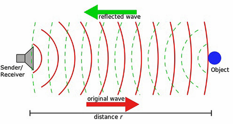
SONAR (SOund Navigation And Ranging) transducers emit sonic pings which bounce off of elements in the environment (figure 1). The time it takes for the ping to return to the transducer is scaled by the speed of sound in the robot's operating medium (i.e., air or water) to determine the distance to the object.
Much like RADAR, SONAR sensors are prone to false positives at close range because of the way the sound waves spread out from the sensor (figure 2). Cross-talk between SONAR transducers can occur when multiple sensors are configured in an array. The transducers sometimes confuse returns from one sensor with the one that they sent out and this can lead to bizarre readings. High-end SONAR transducers sold by P&F and some other companies can be configured to ping one-after-the-other and eliminate cross-talk.
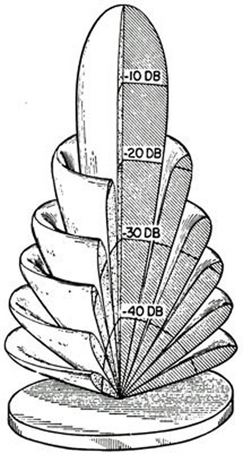
means that these sensors have difficulty at close
range and will report objects that are located
laterally to the sensor as if they were if front.
Air-based SONAR sensors work in the ultrasonic region of the spectrum so people can’t hear the sound waves constantly bouncing but you can often hear a faint clicking sound when your ear is directly in front of them. Underwater SONAR typically sends out pings at a lower frequency which is audible to humans, leading to the classic “PING” sound we all know.
A single SONAR transducer can determine the distance to an obstacle in a robot’s environment. When multiple transducers are placed side by side (multi beam) or a single transducer is configured to scan, typically underwater, SONAR returns, along with localization data from other sensors can be combined to generate 3D images of a robot’s environment.
SONAR as a rangefinder is used widely across robotics. SONAR as an imaging sensor is most typically used only on water-faring robots. Single-transducer open-air SONAR sensors for range-finding can be had for fewer than five dollars on the low end, and several hundred dollars on the high-end. There is a serious difference in performance between these price-points.
SONAR imaging units can be had for several hundred dollars on the low end and run into the six-figure range for government research and military units. Some of the more advanced multi beam imaging units receive multiple returns that bounce off of objects in the environment in different ways for each ping they sent out, and can use this data to report things like underwater vegetation density.
Localization
Localization is the process of keeping track of where a robot is on a map, which is to say relative to some known reference point or its starting point. The above-listed “environmental” sensors can be used for localization by correlating observed features to determine a best guess of something that looks similar on a stored or in-progress map of a robots environment.
Even with the existence of techniques and algorithms for localizing off of observed features of a robot’s environment, most robots utilize specialized sensors for localization in order to more easily and less ambiguously deduce their location on a map.
Dead Reckoning Using Relative Positioning Sensors
The most basic form of localization is a technique known as relative positioning or dead reckoning. Dead reckoning was originally developed for use on sailing ships and refers to the process of deducing a robot’s current position by adding up increments of distance traveled in set direction at known speeds over known timeframes (figure 3).
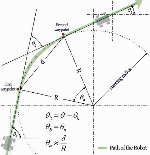
An issue with dead reckoning is that small errors in the system can add up to large errors over time. Therefore, dead reckoning often serves as a calibration point to help reduce the noise from absolute positioning sensors.
One example of this occurs when a robot operating indoors using LiDAR estimates where it might be from the shape of the walls. In this case a rough idea of where the robot is from dead reckoning could narrow down its possible locations, allowing use of the LiDAR range data to compute the location of the robot with a much greater degree of certainty. In some cases, dead reckoning can also serve as a backup means of navigation during a sensor blackout (for example GPS on a self-driving car losing signal in a tunnel).
Encoders
One form of dead reckoning, known as odometry, adds up how many times a robot’s wheels have turned to get a rough idea of where a robot is. As good as it sounds on paper, this is actually a pretty horrible way to keep track of where a robot is for a few reasons.
The most pronounced reason not to use odometry as a primary means of localization is wheel slip. Even in highly controlled indoor environments, wheels on a robot slip. Small amounts of slippage can, over time, completely muddy a picture of where a robot is because unavoidable errors will build on themselves. Figure 4 illustrates an example where a robot’s right wheel is slightly more slippery than its left.
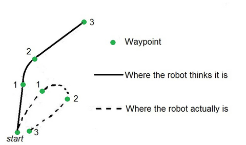
Still, many robots use incremental rotary quadrature encoders, henceforth “encoders,” on their drivetrain to track how much the wheels have turned. One reason why is that it provides a data point to check the robot’s more primary sensors against, to distinguish noise from real data. Another application is to compare encoder values for where a robot should be to where actually is based on other sensors in order to figure out how much a robot’s wheels are slipping. Motor speed can then be adjusted to reestablish grip (traction control).
Encoders are relatively inexpensive. To provide an idea of how low-cost they can be, every five-dollar 90’s-era computer mouse has 2 encoders inside of it. Higher-end encoders for industrial applications (figure 5) can run up to several thousand dollars per unit. Many motors sold for robotics use come with built-in encoders as standard equipment or as an option.

Inertial Measurement Unit (IMU)
An IMU, or Inertial Measurement Unit, is a device which combines one or more (typically 3-axis) gyroscope(s) with one or more (typically 3-axis) accelerometer(s) and sometimes a magnetometer. The IMU can report raw sensor data or use an onboard microcontroller to fuse the data from the various sensors, and provide a pretty good idea of angular acceleration, linear acceleration and sometimes compass heading, which is typically used to extrapolate the position and heading of a robot relative to a known starting location.
IMUs are standard on aerial drones, rockets, submarines and many ground-based robots-including pretty much every self-balancing and walking robot as well as some self-driving cars. Your smartphone also has one that it uses as a GPS alternative when you’re in a parking garage, big city, or dense forest.
A positive aspect of IMUs is that they do not require any type of physical interface to the “outside world” in order to work. They are often used by systems with GPS as an alternative when there is a GPS blackout (that is to say no access to GPS). A negative aspect of IMUs is that over time, IMU measurements, particularly on the lower-end units, will drift because error will build on error, so it is best to check IMU data against other sensors when determining a robot’s location.
Thanks to the smartphone industry, MEMS IMUs can be had in production quantities for under a dollar, making them a good low-cost sensor for consumer facing robots and drones. More expensive IMUs, integrating high-end features such as fiber optic gyroscopes, fluid couplings and magnetic sensors to track the earth’s rotation are priced in the five-figure range. Custom IMU’s used by the defense industry can run six figures. These high-end units are much more accurate than their low-end counterparts and are generally dependable in applications where keeping an accurate idea of where a machine is could be a matter of life or death.
Absolute Positioning
Absolute Positioning uses known landmarks and/or beacons to tell a robot precisely where it is within a certain degree of precision. Absolute positioning data and relative positioning data are often fused with highly accurate results (i.e., millimeter precision).
GPS
GPS (Global Positioning System) receivers constantly track the distance to satellites orbiting the Earth. America, Russia, China, and the European Union all operate some form of a GPS. American GPS, also known as Navstar, is comprised of 31(at the time of this article) active satellites orbiting the earth on known trajectories. So long as enough satellites are visible (figure 18) at any given time, which they usually are in open outdoor spaces due to redundancy in the system, a GPS receiver can use trilateration to determine its position on the globe.
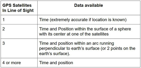
The distance measurements are based off of the fact that each GPS satellite contains a highly accurate atomic clock, and sends out the time at the satellite constantly. The signal is encoded in CDMA in order to distinguish it from other satellites and terrestrial noise. By scaling the difference between the time at the robot’s location and that at the satellite to the speed of light, the distance between the robot and satellite is determined.
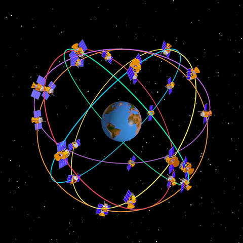
According to gps.gov, high end civilian GPS (SPS) receivers are horizontally accurate to 2.168 meters 95% of the time. Vertical accuracy is not as high. GPS is a good choice for any robot working outdoors. GPS has none of the issues with accumulated error that present on IMUs because it provides absolute position, as opposed to the relative position provided by IMUs integrating acceleration over time.
GPS makes no sense indoors because ceilings block line-of-sight to the satellites. GPS is most accurate when the satellites it is using to find its location are as far apart in the sky as possible. Therefore, GPS is unreliable inside of volcanos, mineshafts, sinkholes, and around skyscrapers. GPS does not work underwater due to attenuation, but some unmanned submarines use GPS to reduce error in their location when they surface in conjunction with IMU’s to keep track of where they have traveled underwater relative to their last known GPS coordinates. Many modern military robots are designed to be able to function without GPS since it is easily jammed on a battlefield- often by the communications jammers used by the same military fielding the robots.
Local Positioning Systems For Controlled Environments
For robots operating in a controlled environment, it can make sense to set up beacons at fixed locations to aid in localization. Beacons are functionally similar to GPS in that the distances to them are used to extrapolate a robot’s absolute position in the context of its environment.
Beacons can be active, meaning they send out a signal all of the time, or passive, meaning they don’t constantly emit a signal but they can be observed or pinged by an associated sensor. The system comprised by beacons and the sensors that detect them is known as a Local Positioning System (LPS).
RTK
RTK (Real Time Kinematic) corrections use one or more local base stations to augment the satellites in a GPS and increase a robot’s certainty of where it is over GPS alone. Trimble, Leica, Topcon, and others all maintain networks of RTK base stations which can be utilized in covered areas with an Internet-connected RTK-capable GPS receiver for an accuracy of 1-2cm. Use of existing base stations is either free or available for a fee- depending on the network. Commercial RTK bridges and repeaters can be deployed as base stations.
Radio Trilateration
Radio Trilateration is an attempt to create a (usually) indoor GPS alternative. For this to work, radio beacons with known locations are incorporated into a map of a robot’s work environment. Issues with radio trilateration include dead-spots, and signal bouncing off of walls and room features to create the illusion of a longer distance to a beacon than there actually is. Some variants of this technology use Wi-Fi access points signal strength, WiMax, and Ultra-Wide Band.
Northstar
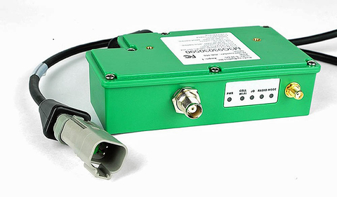
There are many active-beacon-based indoor GPS alternatives that use other means besides radio trilateration. One such product, known commercially as Northstar, uses IR patterns transmitted onto the ceiling of a room to get a robot’s absolute position within 15 cm. While it is far from precise, Northstar is inexpensive and offers a way for a robot indoors to quickly and easily figure out its location without having to rely on any stored data, making it a good fit for consumer robots.
Cameras And April Tags
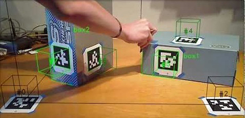
In addition to the active beacons described above, there are also passive beacons. One such example is an April Tag which can be printed on regular printer paper and attached to any visible surface in a robot’s operating environment. The exact location and angular orientation of the tag relative to a robot-mounted camera can be found using readily available CV software and used to localize the robot relative to the tag.
Star Tracking
Star trackers, commonly used on spacecraft and high-flying planes, such as the SR-71 Blackbird, use the relative position of stars in the night sky to determine their location. Many models are available. Obstacles to use include light-pollution from Earth as well as lights and engines on spacecraft.
Combining Sensors For Simultaneous Localization And Mapping
SLAM (Simultaneous Localization and Mapping) is the concept of using multiple sensors on a mobile robot to build a map of the robot’s environment while tracking robot position within that environment. SLAM works by matching geometric or visual features recognized by environmental sensors to the map and correcting errors built up in relative positioning sensor data. If correctly implemented, SLAM can give a robot a more accurate location than any one sensor alone and can work indoors without the use of beacons or any infrastructure.
There are many ways to implement SLAM and there is no perfect SLAM implementation for every scenario. In terms of hardware, any relative positioning sensor(s) can be used along with any environmental sensor(s) as long as the combined sensor allows for some form of depth perception. Combinations of LiDAR and IMUs are common at the time of this article. While the hardware is always a component, the software is key to making it work.
The sensor configuration should be selected based on the relative merits of sensors for the application, cost, and operating environment. In a nutshell, the better-purposed and higher quality of sensors and the more cutting-edge the algorithms used, the more accurate a robot’s map and position.
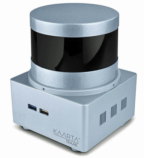
Some companies, such as Kaarta, offer pre-built sensor-fusion packages that ship with working SLAM. Kaarta’s robot-mountable system, Traak, uses high quality sensors and runs one of the best algorithms in the world (Winner of Microsoft’s indoor localization competition for multiple years and top of the KITTE benchmarks) on its internal computer. While most SLAM has drift rates in the 2%, Traak is typically 0.2% drift, an order of magnitude less. It both builds a map of the environment, can be used to determine a path, and follow that path. It is priced at around $27,000 for a single unit plus LiDAR and also available as licensed software at a significantly lower price point.
If an off-the-shelf solution won’t cut it, either because it is too expensive or not suited to a robot’s operating environment, an applications engineer can combine the sensors in this article to come up a tailored system that fits their needs.
Don’t miss Spencer’s session at Sensors Midwest, titled Challenges in Building Robots for Harsh Environments. He will deliver his presentation on Wednesday, October 4, 2017 at 1 PM in Theater 3.
About the author
Spencer Krause, Director of Product Management, SKA
Spencer Krause has been applying the concepts in this article to building robots for over fifteen years. Spencer is the Director of Product Management at SKA (www.ska.solutions), where he and a dedicated team help technology companies to build mechatronics devices, robots, and user interfaces. He has a Master’s Degree in Robotics Systems Development from Carnegie Mellon University where he remains on staff in the Field Robotics Center. In his spare time, Spencer mentors gifted students who are learning about robotics.