
Sensors are the eyes and ears of a mobile robot. They can be used for many things, including but not limited to detecting and making sense of sounds, temperature, humidity, chemical compositions, and many other phenomena. This article focuses on sensors for the identification of features in a robot’s environment and sensors for localization (knowing where a robot is on a map).
Which sensors you should choose for a particular mobile robot depends on several factors- for example; budget, size, and operating environment. Some sensors like encoders in a drive system, are pretty useless in and of themselves, but can be very useful by providing calibration points for filtering IMU data. Other sensors, such as bump sensors, make a lot of sense in consumer applications but can be dangerous on industrial machines where if you touch something it is already too late. The opposite is true for expensive, yet versatile and accurate, LIDAR sensors.
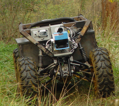
This article will discuss the basic workings and mobile robotics applications of over a dozen types of sensors to give industry professionals a systems-level understanding of when to use what sensor and why. It will not explain how to install, setup, and apply the sensors, but rather help mobile robot designers narrow down their sensor choices from an informed position.
Environment Sensing
The following sensors are used to identify objects and obstacles of interest in a mobile robot’s operating environment. This section discusses using the sensors to see where things are relative to the robot, but it should be noted that the information gathered by many of these sensors can also be used to make an educated guess about where a robot is on a map- a process known as localization and mapping.
Bump Sensors
One of the simplest types of sensors is the bump sensor. A bump sensor uses physical whiskers or typically a plastic bumper to tell a robot when it has collided with an obstacle, be it a wall, a chair, a person or otherwise. Most of the time, bump sensors work by having a mechanical mechanism activate some type of momentary switch, but in the case of some types of whiskers, flex potentiometers can be used to see how far the whisker has been bent and therefore how far into the obstacle the robot drove before getting a command to stop and navigate around it.
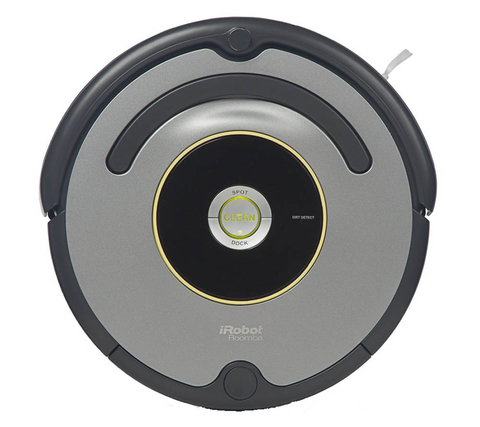
Bump sensors are one of the cheapest things you can put on a robot, usually costing no more than a couple of dollars, even at small scales. This makes them a popular choice for low-cost consumer robots. Industrial robot builders should be cautious about using this kind of sensor on or around expensive and/or dangerous equipment. The implications of industrial collisions can be devastating and so it is usually worth the extra cost to build a system that detects obstacles before physically contacting them. If they are used at all, bump sensors in industrial applications, usually in the form of limit switches, are typically used as the sensor of last resort if all other sensors have failed to detect an imminent collision.
Infrared Range Finding
One non-contact method for detecting obstacles uses infrared emitters and receivers (usually an LED and a photodiode with some basic circuitry). In this type of sensor, the emitter sends out a pulse of infrared light and if the same pulse is detected on the receiver within a set amount of time there is deemed to be an obstacle close to the robot. A slightly more advanced version of this sensor can scale the amount of time it takes for a pulse of IR light to go from the emitter to the obstacle back to the sensor and provide a distance to that obstacle.
Basic IR ranging sensors can be built or bought for under $10, making them a good choice for consumer and educational robots. It is important to note that variations on this technology are currently being explored by companies like LeddarTech as a low-cost alternative to solid state LiDAR, discussed below.
LiDAR
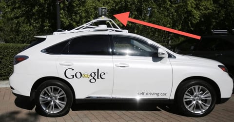
LiDAR (Light Detection and Ranging) traditionally uses a series of laser pulses in a scanning pattern to generate a “point cloud” of a robot’s environment. An example point cloud is pictured in Fig 4.
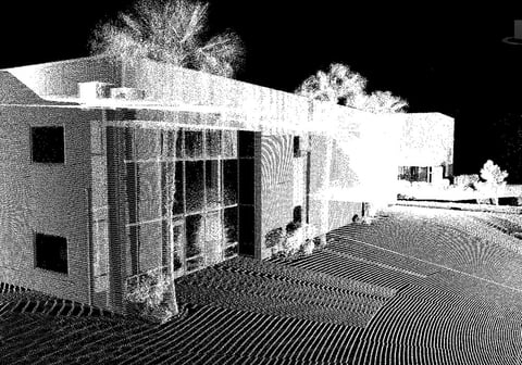
LiDAR sensors constantly send out LASER pulses and see how long it takes them to bounce off of objects and return to the sensor. The time it takes for a LASER pulse to hit an object and bounce back to the sensor is scaled to give the distance to a small part of that object. Combining these distance measurements in a common coordinate system generates a point cloud. Point clouds can be used to supplement or create maps of all of the opaque objects in a robot’s field of vision, track objects, or build 3D models. LiDAR sensors typically have a range of 30 to 120 meters, and are reliable in outdoor environments- a rarity for optical sensors given the brightness of the sun.
LiDAR units are relatively expensive, costing anywhere from $1,000 to $100,000. That said, the units are expected to go down in price as the automotive industry adopts the technology on a wider scale. An additional downside which some of our clients struggle with is that LiDAR cannot reliably detect optically transparent materials, such as plate glass, and should therefore be supplemented with other sensors such as RADAR or SONAR in environments where not being able to detect something transparent could present an issue.
Solid State LiDAR
A more modern LiDAR system, still in its infancy at the time of this article, is solid state LiDAR. Solid state LiDAR does away with moving parts to decrease both cost and latency of taking readings at multiple BEAM angles. As with any new technology, the prototype units on the market in the past couple of years have very limited resolutions and ranges and are currently rather expensive. That said, the technology is projected to rapidly become less expensive and more reliable than traditional scanning LiDAR. Velodyne recently announced development and testing of a small solid state LiDAR system, dubbed Velarray (Fig 5).
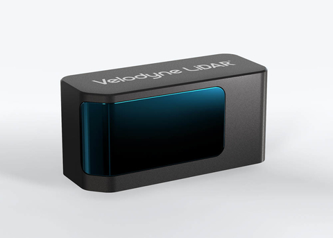
The system has a compact package of 125mm x 50mm x 55mm, and provides a 120 degree horizontal and 35 degree vertical field of view. It is in pre-production at the time of this article, with the first production units expected to roll off of the assembly line in early 2018.
RADAR
RADAR, which stands for RAdio Detection And Ranging, is a means of using a directed radio wave to determine how far away an object is, how fast it is going (Doppler RADAR) and it's rough shape and size. RADAR bounces radio waves off of a robot’s environment to get the distance to whatever RADAR-reflective object it is pointed at.
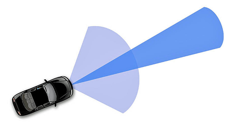
Electronically Scanned RADAR (ESR) uses electronics to steer the direction of a RADAR beam and create a point cloud. ESR units are common on self-driving cars and autonomous industrial fleet vehicles for fusion with LiDAR data and to monitor blind-spots.
RADAR is a natural choice in military applications where you want to be able to detect and track faraway objects before they become a threat. RADAR waves typically go through plastic, meaning you can house RADAR sensors inside a car bumper without compromising the aesthetic of the vehicle.
One phenomenon with RADAR occurs when a RADAR wave bounces off of ground, the atmosphere, or objects in a robot’s operating environment in an unexpected way to make the distance and direction to a target seem longer/ different than it actually is are or to give multiple returns on a ping (Fig 7).
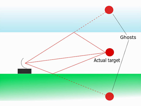
This can lead to ambiguity as to where an object really is. That said, high-end sensors and algorithms can make order of the chaos and use multiple returns on a signal sent out to derive additional information about the environment.
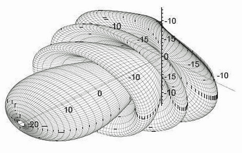
In addition, RADAR units can return false positives at close range due to the lobe structure shown in Fig 8. For example, an item off to the side of a unit could register as being in the same place as an item directly in front. As a result, RADAR performs best at longer ranges.
RADAR units are relatively expensive, which mostly limits them to industrial, military, and automotive use.
Cameras
The most basic camera system on a mobile robot uses a single camera to sight objects of potential interest in the visual and infrared regions of the spectrum. Most cameras, including the one in your cell phone, capture infrared light.
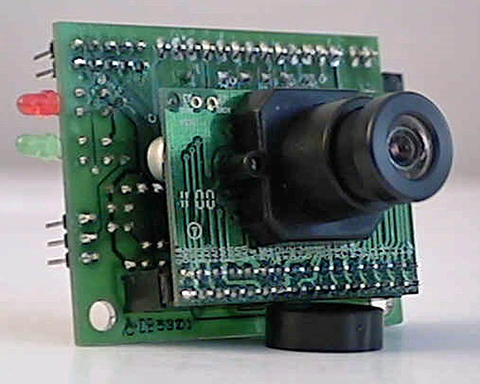
Among many other things, relative locations and centers of mass of various objects in the camera’s field of view can be determined using basic algorithms. Many computer vision (CV) software packages are now available, so there is not always a need for integrators to write or even understand CV algorithms in order to implement them.
Changing the amount and direction of light can significantly affect a robot’s perception and determining distance requires additional hardware.
Accessorizing the system
Illumination And Night Vision
It is common for robotics camera systems to be supplemented by fixed lighting, even in well-lit environments. One reason for this is that if the robot contains a light source more or comparably powerful at close range than light in its environment, the effect of ambient light on the camera images becomes less pronounced compared to the robots “headlights” and it is one less variable to worry about in software.
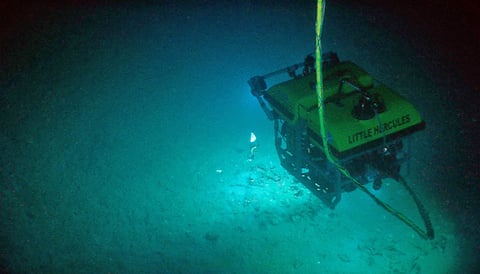
Similarly, an easy kind of “night vision” can be achieved by mounting infrared spotlights to the robot and/or the camera. This light source is invisible to humans, but visible to pretty much every unfiltered visible light camera on the market. Cameras on robots operating in outdoor environments should be “shrouded” from direct sunlight by attaching a visor to the camera.
Depth Perception
Stereo Vision
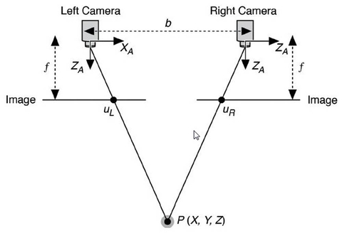
By adding a second camera in-plane with the first, stereo vision, the means by which humans perceive depth, can be achieved. With stereo vision, distance to common features in the two images is extrapolated by comparing the relative positions of those features on their respective images, and factoring in known parameters about the camera system such as focal length of the cameras (f in fig 11), and camera spacing (b in fig 11).
Structured Light
Attaching a LASER pointer facing the same direction as a camera in a single camera system with a known position relative to the camera adds a reference point to that camera's field of view that “moves” on camera’s image depending on how far away the thing it is pointing at is from the system. Distance to that object can then be extrapolated using trigonometry, similar to that used for stereo vision (Fig. 11). This is the most basic example of structured light.
Certain sensors, notably early versions of the Microsoft Kinect and several fast followers, take this idea a step further by projecting a unique pattern of dots over an image in the infrared spectrum. These types of sensors use their knowledge of the pattern being projected to apply the LASER pointer logic across an entire image.
In the right environment, i.e.: indoors at close range, this setup is less software-intensive and can be more reliable than a stereo-camera setup because it doesn’t require the software to identify sometimes ambiguous common features across multiple images. Since they rely on projected patterns, structured light sensors cannot be confused by optical illusions in the same way as stereo vision, but mirrors can still present an issue.
The majority of structured light sensors must be used indoors as sunlight can render the projected pattern unreadable. SICK recently released a sensor utilizing this principle that claims to work in sunlight, but the practical results outside still leave much to be desired.
In part two next week, Spencer finishes up with insights into various complex devices for completing the robotic system. Most importantly, don’t miss Spencer’s session at Sensors Midwest, titled Challenges in Building Robots for Harsh Environments. He will deliver his presentation on Wednesday, October 4, 2017 at 1 PM in Theater 3.
About the author
Spencer Krause has been applying the concepts in this article to building robots for over fifteen years. Spencer is the founder of SKA (http://www.spencerkrause.com), a consulting firm, where he and a dedicated team help technology companies to build mechatronics devices, robots, and user interfaces. He has a Master’s Degree in Robotics Systems Development from Carnegie Mellon University where he remains on staff in the Field Robotics Center. In his spare time, Spencer mentors gifted students who are learning about robotics.