
 The optical system of any conventional photoelectric sensor is designed for one of three basic sensing modes: opposed, retroreflective, or proximity. And the photoelectric proximity mode is further divided into five sub-modes: diffuse, divergent-beam, convergent-beam, fixed-field, and adjustable-field proximity. Each sensing mode has its own unique set of operating characteristics. If you know how each mode works, you can match the right configuration with the right application.
Opposed Mode
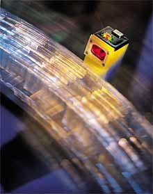
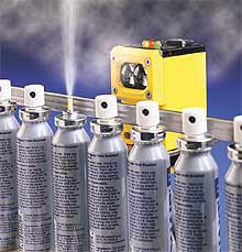
Opposed-mode sensing is often referred to as throughbeam sensing or is sometimes called the direct scanning mode. In this mode, the emitter and receiver are positioned opposite each other so that the sensing energy from the emitter is aimed directly at the receiver. An object is detected when it interrupts the sensing path between the two components (see Photo 1).
 |
| Photo 1. Opposed-mode (or throughbeam) photoelectric sensing uses an emitter and a receiver positioned opposite each other. Opaque objects are sensed when the beam is blocked. Small profiles can be sensed by using lens apertures or a modulated laser emitter (shown here). |
Alignment involves positioning the sensor so that the maximum amount of emitted energy reaches the receiver. In opposed sensing, this means that the emitter and the receiver are positioned relative to each other so that the radiated energy from the emitter is centered on the field of view of the receiver. In the early days of nonmodulated photoelectrics, problems with emitter-receiver alignment gave this mode a bad reputation. But with today's high-powered modulated designs and alignment systems, it's easy to align most opposed-mode sensors.
The sensing range of this type of sensor is the maximum operating distance between the emitter and the receiver. A sensor's effective beam is the working part of the beam: it is the portion of the beam that must be completely interrupted for an object to be reliably sensed. The effective beam of an opposed-mode sensor can be depicted as a rod that connects the emitter lens to the receiver lens (see Figure 1). The rod will be tapered if the two lenses are of different sizes. The effective beam should not be confused with the radiation pattern of the emitter or with the field of view of the receiver.
The effective beam size of a standard opposed-mode sensor can be too large to detect small parts, inspect small profiles, or accurately sense position. In such cases, the sensor's lenses can usually be apertured to reduce the size of the effective beam. Some opposed-mode sensors have optional aperture assemblies that mechanically attach to the lens. Creating an aperture can be as easy as drilling a hole or milling a slot in a thin metal plate located in front of the lens, with the opening on the lens centerline. When selecting aperture material, it's important to remember that the powerful beam of modulated, opposed-mode photoelectric sensors can penetrate many nonmetallic materials to varying degrees.
 |
| Figure 1. The effective beam of opposed-mode sensors is the portion of the beam that must be completely blocked for an object to be reliably sensed. It can be depicted as a rod connecting the emitter lens to the receiver lens. |
Apertures reduce the transmitted light energy by an amount equal to the lens area reduction. For example, if a 1 in. dia. lens is apertured down to 1/4 in. dia., the amount of optical energy passing through the apertured lens is equal to (1/4)2 = 1/16 the amount of energy through the 1 in. lens. The energy loss is doubled if apertures are used on both the emitter and the receiver.
A rectangular aperture covers much less light-gathering lens area than does a round aperture of the same width (diameter). For this reason, rectangular apertures (also called slit apertures) should be used whenever possible. Rectangular apertures are reliable when an object travels into the beam with a predictable orientation to the effective beam (as in edge detection). When objects with small profiles move through the beam with random orientation, round apertures are required.
If the object to be detected will always pass close to either the emitter or the receiver, an aperture may be required on only one side of the process. In this case, the size of the effective beam is equal to the size of the aperture on the apertured side and uniformly expands to the size of the lens on the unapertured side. The effective beam is therefore cone shaped.
 |
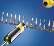
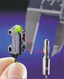
| Photo 2. The retroreflective sensing mode establishes a beam between the sensor and a retroreflective target. Objects are sensed when they interrupt the beam. Visible emitters make alignment easy. |
The goal in an application requiring the detection of small parts by an opposed-beam sensor is to make the size and shape of the effective beam smaller than the smallest profile that will ever have to be detected while retaining as much lens area as possible. Often the easiest way to match the size and shape of an effective beam to a part profile is to use a glass fiber-optic assembly that has its sensing end terminated in the desired shape.
The high power of some modulated LED opposed-mode sensors (especially when used at close range) can create a flooding of light energy around an object equal to or slightly larger than the effective beam. This is another reason to ensure that the size of the effective beam is smaller than the profile of the object to be detected.
Laser diode emitters are a practical alternative to apertured conventional opposed-mode sensors. The laser-based sensors can produce narrow effective beams over extended ranges. These devices are useful in such applications as small object detection and precise position control (see Photo 1).
Retroreflective Mode
This sensing mode is also called the reflex mode, or simply the retro mode. A retroreflective sensor contains both emitter and receiver circuitry. A light beam is established between the emitter, the retroreflective target, and the receiver. As in opposed-mode sensing, an object is sensed when it interrupts the beam (see Photo 2).
The retroreflective range is the distance from the sensor to the retroreflective target. The effective beam is usually cone shaped and connects the periphery of the retro sensor lens (or lens pair) to that of the retroreflective target. The exception to this occurs at close range, when the size of the retro beam has not expanded enough to at least fill the target. The size of a retroreflective beam is usually not of concern because retro sensors are most often used for sensing large objects. However, when a small effective beam is required, consider either opposed-mode sensors or a retroreflective sensor that uses a laser diode as its light source.
 |
| Figure 2. Another way to reduce retroreflective proxing is to use polarizing filters. Emitted light is vertically polarized. Corner-cube retro targets rotate the reflected light by 90º. Light reflected from a shiny surface is not rotated. A horizontal polarizing filter placed ahead of the receiver accepts the light from the retro target and rejects light reflected from a shiny surface. |
Most retroreflective targets (also called retroreflectors or retro targets) are made up of many small corner-cube prisms, each of which has three mutually perpendicular surfaces and a hypotenuse face. When a light beam enters a prism through its hypotenuse face, the three mutually perpendicular surfaces reflect the beam back through the hypotenuse face parallel to the entering beam. In this way, the target returns the light beam to its source.
Most corner-cube retroreflectors are molded acrylic plastic, manufactured in various sizes, shapes, and colors. These retroreflectors are commonly used for highway markers and vehicle safety reflectors. Retroreflectors appear brightly illuminated to a driver when light from a vehicle's headlamps is returned by the array of corner cubes. Highway markers are often wrapped in retroreflective tape, which has a covering of either many microscopic molded corner-cube reflectors or microscopic glass beads. A clear glass sphere can return a light beam back to its source, but a coating of glass beads is not as efficient a reflector as a molded array of corner cubes.
A mirrored surface can also be used with a retroreflective sensor. But light striking a flat mirror surface is reflected at an angle equal and opposite to the angle of incidence. This is called specular reflection. For a retroreflective sensor to see its light reflected from such a surface, you must position the sensor so that its emitted beam strikes the mirror exactly perpendicular to its surface. On the other hand, a retroreflector can return incident light back to its source at angles up to ~20º from the perpendicular. This property makes retroreflective sensors easy to align with their retro targets.
A good retroreflector returns ~3000 times as much light as does a piece of white typing paper. This is why it's easy for a retroreflective sensor to recognize only the light returned from its retroreflector. If the object interrupting a retroreflective beam is highly reflective, the object may slip through the retroreflective beam without being detected. You can deal with this sensing problem (which is called proxing) by using some relatively simple methods.
If a shiny object has flat sides and passes through a retroreflective beam with a predictable orientation, the cure for proxing is to orient the beam so that the object's specular surface reflects the beam away from the sensor. This is called scanning at a skew angle to the object's surface. The skew angle usually has to be only 10º15º (or more) to be effective. This solution to proxing may, however, be complicated if the shiny object has a rounded (radiused) surface or if the object presents itself to the beam at an unpredictable angle. In these cases, the best mounting scheme, although less convenient, has the beam striking the object at both a vertical and a horizontal skew angle.
 |
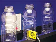
| Photo 3. In the diffuse sensing mode, the emitted light strikes a surface at some arbitrary angle. The light is then diffused from the surface at many angles. A small portion of the light will reach the receiver. |
With improvements in LED technology, the use of visible light LEDs as photoelectric emitters has increased. When equipped with a visible emitter, a retro sensor can be aimed like a flashlight at its retroreflective target. When the reflection of the beam is seen on the retroreflector, correct alignment is ensured. This principle is also of benefit when a visible emitter is used in an opposed-mode photoelectric system. A retro target is placed in front of the receiver's lens, and the emitter is aligned by sighting the visible beam on the target. The retro target is then removed, and the emitter and receiver orientations are fine-tuned for optimum alignment.
Polarizing filters are readily available for use with visible emitters. When used on visible retroreflective sensors, polarizing filters (sometimes called anti-glare filters) can significantly reduce the potential for proxing. First, you place a filter in front of both the emitter lens and the receiver lens. Then you orient the two filters so that the planes of polarization are at 90º to one another. When the light is emitted, it's polarized vertically (see Figure 2). When the light reflects from a corner-cube retro target, its plane of polarization is rotated 90º, and only the polarized target-reflected light is allowed to pass through the polarized receiver filter and into the receiver. When the polarized emitted light strikes the shiny surface of the object being detected, its plane of polarization is not rotated, and the returned nonpolarized beam is blocked from entering the receiver.
This scheme effectively reduces proxing. But polarizing filters, like a good pair of sunglasses, reduce the optical power available in a retro beam by more than 50%. This is an important consideration when the environment is dirty or the sensing range is long. Also, polarized retro sensors work only with corner-cube retroreflective materials. Often, the best insurance against proxing is the skew angle approach. When this isn't possible, opposed-mode sensors should be considered.
Proximity Mode
Proximity-mode sensing involves detecting an object directly in front of a sensor by detecting the sensor's own transmitted energy reflected back from the object's surface. In proximity sensing modes, an object, when present, actually makes (establishes) a beam rather than interrupts the beam. Photoelectric proximity sensors have several different optical arrangements: diffuse, divergent, convergent beam, fixed field, and adjustable field.
 |
| Photo 4. Convergent-beam sensors focus the emitted light on a point in front of the sensor and focus the receiver element on the same point. The result is a small, intense, and well-defined sensing area centered at a fixed distance from the lens. |
Diffuse Mode. In this mode, the emitted light strikes the surface of an object and is then diffused at many angles. Even when the receiver is located at an arbitrary angle, a small portion of the diffused light will reach it (see Photo 3).
The diffuse mode is inefficient because the receiver works with a small amount of light that is bounced back from a surface. And like other proximity sensing modes, the diffuse mode is dramatically influenced by the reflectivity of the surface that is being sensed. A bright white surface will be sensed at a greater range than a dull black surface. Most diffuse-mode sensors use lenses to collimate (i.e., make parallel) the emitted light rays and to gather more received light.
Although lenses extend the range of diffuse sensors, they also increase the criticality of the sensing angle to a shiny or glossy surface. Because all such surfaces are mirror-like to some degree, the reflection is more specular than diffuse. Most diffuse sensors can guarantee a return light signal only if the shiny surface of the material presents itself perfectly parallel to the sensor lens. This is usually not possible with radiused parts, such as bottles or shiny cans. It is also a concern when detecting webs of metal foil or poly film, when there may be web flutter.
Divergent Mode. To avoid the effects of signal loss from shiny objects, consider using special short-range, unlensed, divergent-mode sensors. By eliminating collimating lenses, the sensing range is shortened, but the sensor is also much less dependent on the angle of reflection of the light from a shiny surface falling in its range.
The range of any proximity-mode sensor also may be affected by the size and profile of the object being detected. A large object that fills the sensor's beam will return more energy to the receiver than a small object that only partially fills the beam.
A divergent sensor responds better to objects within ~1 in. of its sensing elements than does a diffuse-mode sensor. As a result, divergent-mode sensors can successfully sense objects with small profiles (e.g., yarn or wire).
Convergent-Beam Mode. Another proximity mode effective for sensing small objects is the convergent-beam mode. Most convergent-beam sensors use a lens system that focuses the emitted light on an exact point in front of the sensor and focuses the receiver element on the same point. This design produces a small, intense, and well-defined sensing area a fixed distance from the sensor lens (see Photo 4).
This is an efficient use of reflective sensing energy. Convergent-beam sensors reliably sense objects with small profiles and materials of low reflectivity that cannot be sensed with diffuse or divergent mode sensors.
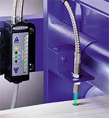 |
| Photo 5. Fiber-optic sensors using visible LED emitters are popular for solving challenging color-mark detection applications. A randomly mixed bundle of glass fiber-optic strands--where one-half of the bundle carries emitted light and the other half carries reflected light to the receiver--is ideal for sensing color differences. |
The range of a convergent-beam sensor is defined as its focus point, which is fixed. This means you must closely control the distance between the sensor and the surface being sensed. These sensors will detect an object of a given reflectivity at its focus point, plus or minus some distance. The sensing area--centered on the focus point-- is called the sensor's depth of field. The size of the depth of field depends on the sensor design and the reflectivity of the object sensed.
Color mark sensing (or register mark sensing) is a specialized application in which a precisely focused convergent device senses register marks in situations usually involving product positioning. The best optics for color sensing are those that receive light in exactly the same pattern as the emitted light. This is true for convergent beam optics, and it's also the nature of a randomly mixed bifurcated glass fiber-optic bundle. For this reason, fiber-optic sensors are popular for solving color mark sensing challenges (see Photo 5). LED color is important in determining the color contrasts that can be sensed. Color mark sensors that use new white LEDs can discern contrasts as slight as 20% yellow on white.
Laser diode convergent sensors produce a small concentrated focus point. Typically, laser diode convergent-beam sensors produce a focus point only 0.25 mm in diameter at a sensing distance of 100 mm. Such sensors are ideal for use in small parts detection and as robotic end effectors. Laser convergent sensors, with their high sensing power, can often detect objects not reflective enough to be sensed with conventional LEDs.
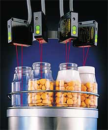 |
| Photo 6. Fixed-field and adjustable-field sensors offer proximity-mode sensing and the advantage of a cutoff point beyond which reflections are ignored. Adjustable-field sensors (shown here) allow the cutoff point to be easily dialed in. |
It's often necessary to detect objects that pass within a specified range of the sensor while ignoring other stationary or moving objects in the background. One advantage of convergent-beam sensors is that objects beyond the far limit of the depth of field are ignored. It's important to remember, however, that the near and far limits of a convergent-beam sensor's depth of field are dependent on the reflectivity of the object in the scan path. Background objects of high reflectivity will be sensed at a greater distance than objects of low reflectivity.
Fixed-Field Mode. Fixed-field sensors have a definite limit to their sensing range: they ignore objects that lie beyond their sensing range, regardless of object surface reflectivity.
Fixed-field sensors compare the amount of reflected light seen by two differently aimed receiver optoelements. A target is recognized as long as the amount of light reaching receiver R2 is equal to or greater than the amount seen by R1. The sensor's output is canceled as soon as the amount of light at R1 becomes greater than the amount of light at R2.
Adjustable-Field Mode. The receiver element of an adjustable-field sensor produces two currents: I1 and I2 (Photo 6). In adjustable-field sensing, the ratio of the two currents changes as the received light signal moves along the length of the re-ceiver element. The sensing cutoff distance relates directly to this ratio, which is made adjustable by using a potentiometer. Even objects with highly reflective surfaces that are located beyond the cutoff distance (example: object B) are ignored.
Summary
Photoelectric sensors are used in a wide range of applications, influenced by an array of operating conditions. Understanding the differences among the available photoelectric sensing modes is the first step toward determining which sensor will work best in an application and why. Other sensing variables include environmental factors (e.g., humidity, temperature, dirt, hazardous atmosphere, vibration, and electrical noise), required sensing speed, available sensor mounting space, interface requirements (e.g., AC/DC, analog discrete, electromechanical load, solid-state input, and device-level bus network), and sensing contrast. Each of these variables is worthy of discussion. Hopefully, this primer has shown how understanding sensing modes will help you select the best photoelectric sensor for your application.
This article was adapted from the "Sensing Theory Primer."