

With each succeeding equipment generation, industrial equipment manufacturers demand ever better system performance. Today's industries require faster and more accurate equipment with higher machine throughput. These critical positioning applications need absolute encoders to gain the necessary position reliability not achievable by incremental encoders.
Furthermore, the battery backup system limits the overall reliability of the motion-control positioning system. An example of one solution, AZ closed-loop servo system performance can be greatly enhanced by using a new and affordable battery free compact magnetic sensing multi-turn absolute encoder.
Absolute Encoder Limitations
One of the major limitations in using absolute position encoders is the need to remember where they are positioned. Traditionally these high-performance closed-loop systems utilize multi-turn absolute encoders with battery backup that normally retains the encoder position when powered down. The use of a battery system has a limited charge and life expectancy, lasting at best about two weeks when not connected to a power supply.
Batteries are now under stronger regulations during transportation events. In this case, they are restricted to power down conditions. Once received and set up for operation, the complete closed-loop step motor and drive system with an absolute encoder requires a reinitiating of the encoder's home position.
Battery life limitations typically lead to a three to four year life. Once the battery is replaced, the conventional encoder's home position needs to be reset as well.
The Mechanical Absolute Encoders Structure
One motion-control company, Oriental Motor, is using a combination of a magnetic sensor and a number of non-magnetic gears to achieve absolute positions. There is a two-pole magnet at the center of the encoder structure and a multi-pole magnet structure on the magnetic sensor periphery (see figure 1).
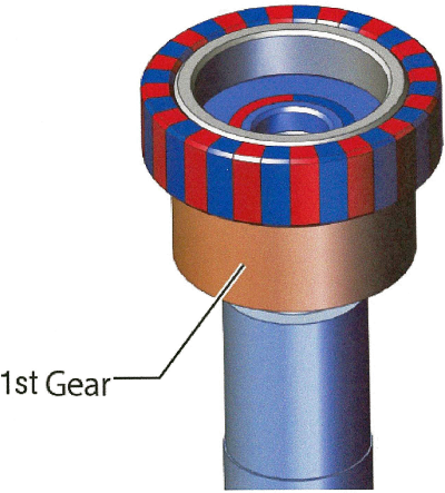
Fig. 1: Dual Magnetic sensor on center shaft. Red (Npole) & Blue (Spole) are identified with gear 1 below.
The inner two-pole magnet's flux is read by the magnetic sensor and this magnetic measurement is combined with the multi-pole magnet signals to create a magnetic flux phase difference that establishes accurate position coordinates. The use of the magnetic position sensor (encoder) provides a high accuracy signal that switches step motor phases at its optimum point ensuring the highest shaft torque available from the motor. This condition results in reduced motor heat generation and lower current draw.
Next page
One gear (first gear) is placed directly on the motor shaft. Two gears (second and third) are placed adjacent to the first gear in parallel columns. The first column has a two-level engagement with the first gear engaging with the second gear below the third gear engaging with the second gear. A separate support column positions the fourth gear to mesh with the first gear (see figure 2).
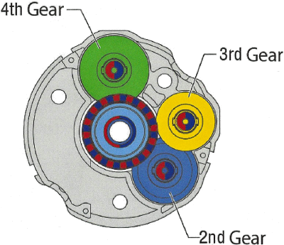
Fig. 2: Top View of Multi-turn absolute encoder gears 2, 3, and 4.
Each gear possesses a different number of gear teeth. The phase position differences with each gear rotation and motor shaft rotation provides the angular increment based on the overall gear tooth pitch, as seen in figure 3.
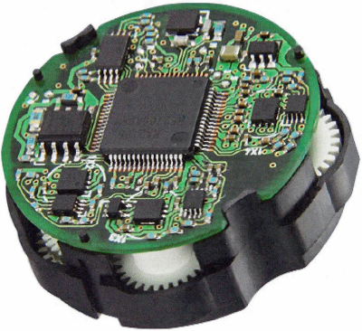
Fig. 3: The electronic detection system structure.
Based on the combination of the various gear-phase angular differences, a multi-rotation coordinate or shaft position increment analogous to the incremental encoder pulse or single position signal is created. The gear phase difference will return to their initial states after rotating 1,800 times. Each full gear rotation leads to 1.800 unique discrete absolute positions.
It is possible to detect backlash as long as it is within a single gear-tooth pitch or angular increment. The gears must be non-magnetic so that they do not interfere with the directions of magnetic flux created by the dual magnet sensor structure. A number of polymers including resins are used due to their self lubricating and low wear capabilities. The various gears are under near no load condition since they are used only for phase and position detection.
Electronic Detection Circuitry
Electronic circuitry shown in figure 3 detects the two magnetic sensor signals and, through a software algorithm, creates a unique position signal or encoder count. Selecting a home position during setup is achieved by just pressing a button on the electronic structure's surface.
Mechanical Encoder Durability
In order to prove the magnetic sensor based mechanical multi-turn absolute encoder's ruggedness, a number of longer-term environmental tests are run. The first is a unidirectional test to ascertain if the resin gears exhibit any high wear and abrasion. It is run at +85°C ambient (maximum specification temperature) at 1,600 rpm motor speed for 7,000 hours.
A second environmental test focusing on bi-directional operation performing 200 million forward and reverse cycles at +85°C ambient is performed limiting the motor acceleration to 54.6 Kilo-radians per second squared. There is no measurable increase in back lash between gears over the extended test time of 7000 hours in unidirectional operation. The bidirectional tests are based on the number of forward – reverse cycles. The test was operated 200,000,000 times without any missteps.
Conclusion
The AZ series, a closed loop stepper system, will utilize the new mechanical magnetic sensing absolute encoder. A fixed reference home position is initially established and eliminates the need to perform frequent return-to-home operations. Thus, the AZ system has the use of a more accurate, reliable, battery free position system.
About the Author
Dan Jones is the President of Incremotion Associates Inc. He received his BSEE degree from Hofstra University in 1965 and MS in Mathematics at Adelphi in 1969. Dan has over 50 years experience in the design of all types of electric motors and generators from 10W to 500 kW and has held engineering design and management and marketing management positions at a number of companies. He is recognized as an international authority on electric motors and motion control. For more details, visit http://incremotion.com.
Related Stories
An Encoder Trade Secret Revealed
MDT Announces TMR3101 Absolute Rotary Encoder
InvenSense Announces Virtual Reality Display Inertial Sensor